

Process for making an aircraft having a floor
- Summary
- Abstract
- Description
- Claims
- Application Information
AI Technical Summary
Benefits of technology
Problems solved by technology
Method used
Image

Examples
first embodiment
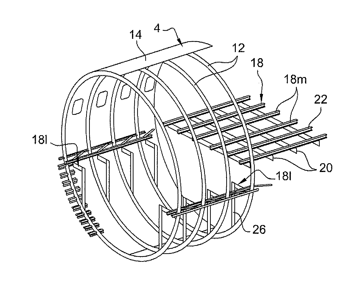
[0057]In a first embodiment, the segment contains a floor 18 comprising two lateral portions 18l, respectively left and right portions, and a middle portion 18m. The middle portion 18m extends between the lateral portions 18l. The overall shape of the floor 18 is generally that of a horizontal plane.
[0058]The middle portion 18m has crossmembers 20 formed by rectilinear section members extending in the direction Y. The crossmembers 20 are parallel to one another, facing one another, and spaced apart from one another. They all lie in the same plane. The middle portion 18m also has rails 22, likewise formed by rectilinear section members extending parallel to one another, facing one another, and spaced apart from one another, but this time along the direction X. All of the rails 22 lie in the same plane. The rails are fastened to the crossmembers 20, with the bases of the rails being in contact with the tops of the crossmembers.
[0059]With reference in particular to FIG. 3, which shows ...
second embodiment
[0074]the invention is shown in FIGS. 9 to 11. Elements that are not described again below are identical to elements of the above-described embodiment.
[0075]The battens 24 and the crossmembers 20 are once more channel-section members. Nevertheless, they are now fastened together back-to-back such that in this embodiment the outside faces of these two section members are in contact with each other. Likewise in this embodiment, the two channel-section members are generally of the same shape and of the same dimensions such that the top and bottom edges of the section members are coplanar, as shown in FIG. 11. Fastening is provided by rivets passing through the two overlapping walls in the direction X.
[0076]In this embodiment, the posts 26 are cylindrical in shape. Each post 26 is connected via its top and bottom ends to a lug in the form of a fitting 36 by means of a hinge about an axis 38 parallel to the direction X. The bottom fitting is rigidly fastened to the frame 12, while the to...
third embodiment
[0078]the embodiment is shown in FIGS. 12 to 16.
[0079]This time, the battens 24 are I section members except at their outer ends where they present only a plane web perpendicular to the direction X and coming into area contact against the plane wall of the frame 12. Each of the crossmembers 20 also presents a I section. The shape and the dimensions of this section are the same as those of the section of the batten. Each batten is rigidly fastened to the crossmember by extending in line therewith. For this purpose, the inside end of the batten and the end of the crossmember have their bottom edges resting on the fitting 36 of the post 26, to which they are fastened by means of rivets. Similarly and as previously stated, the rail 22 rests on the top edges of the batten and of the crossmember, to which it is directly fastened by means of rivets. It is solely by means of this fitting and this rail that the fastening is provided in this embodiment between the batten and the crossmember, ...
PUM
| Property | Measurement | Unit |
|---|---|---|
| Shape | aaaaa | aaaaa |
| Mechanical properties | aaaaa | aaaaa |
Abstract
Description
Claims
Application Information