Method and apparatus for receiving signal for MIMO system

a technology of mimo and receiver, applied in the field of method and apparatus for receiving signals for a multiple input multiple output (mimo) system, can solve the problem of low performance of the mimo receiver, and achieve the effects of reducing hardware complexity, removing interference, and improving reception performan

Inactive Publication Date: 2013-03-26
ELECTRONICS & TELECOMM RES INST
View PDF12 Cites 0 Cited by
  • Summary
  • Abstract
  • Description
  • Claims
  • Application Information

AI Technical Summary

Benefits of technology

[0020]A receiving method and apparatus for a multiple input multiple output (MIMO) system according to an embodiment of the present invention perform a QR operation on a received signal, calculate a log likelihood ratio (LLR) through multiple dimension detection, regenerate a symbol corresponding to a demodulated data stream using the LLR, remove interference from the output vector of the QR operation using the regenerated symbol, performing zero forcing using a weight for the interference removed output vector and the inverse matrix, the result of zero forcing is demodulated. Therefore, reception performance can be improved with hardware complexity reduced.

Problems solved by technology

As described above, the MIMO receiver has a problem of low performance although the MIMO receiver has a comparative simple structure compared to maximum likelihood detection (MLD).

Method used


Image

  • Method and apparatus for receiving signal for MIMO system
  • Method and apparatus for receiving signal for MIMO system
  • Method and apparatus for receiving signal for MIMO system

Examples


Embodiment Construction

[0035]The advantages, features and aspects of the invention will become apparent from the following description of the embodiments with reference to the accompanying drawings, which is set forth hereinafter. Therefore, those skilled in the field of this art of the present invention can embody the technological concept and scope of the invention easily. In addition, if it is considered that detailed description on a related art may obscure the points of the present invention, the detailed description will not be provided herein. The preferred embodiments of the present invention will be described in detail hereinafter with reference to the attached drawings.

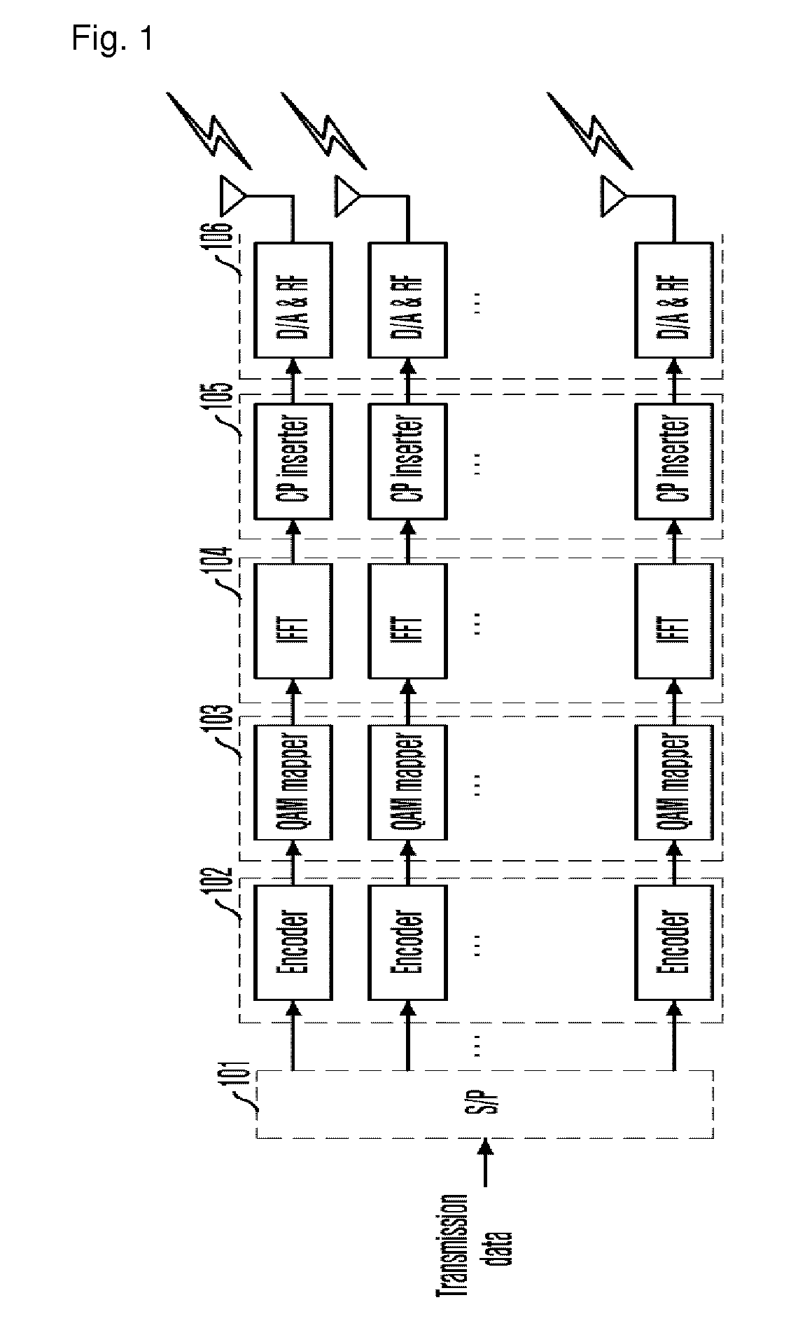
[0036]FIG. 3 is a block diagram schematically illustrating a transmitting end of a multiple input multiple output (MIMO) orthogonal frequency division multiplexing (OFDM) system where the present invention is applied.

[0037]Referring to FIG. 3, the transmitting side includes a serial / parallel (S / P) converter, g encoders 201, q quad...


PUM


Abstract

Provided is a method and apparatus for receiving a signal for a MIMO system. The receiving apparatus includes: a QR decomposer for calculating a unitary matrix Q, an upper triangle matrix R, and a vector size for a received signal; a multiple dimension detector for calculating a first LLR for an output of the QR decomposer through multiple dimension detection; an inverse matrix and weight calculator for calculating an inverse matrix for the upper triangle matrix R and a weight; an interference remover for regenerating a symbol for a demodulated data stream using the fist LLR and removing interference from an output vector of the QR decomposer using the regenerated symbol; and a weight zero forcing unit for performing zero forcing on the interference removed output vector from the interference remover using the inverse matrix of the upper triangle matrix R and the weight and calculating a second LLR.

Description

TECHNICAL FIELD[0001]The present invention relates to a method and apparatus for receiving a signal for a multiple input multiple output (MIMO) system; and, more particularly, to a method and apparatus for receiving a signal for a MIMO system, which improve reception performance with hardware complexity reduced by re-generating a symbol corresponding to a data stream demodulated by a multidimensional detector and demodulating remaining signals after removing the re-generated symbols from a received signal.[0002]This work was supported by the IT R&D program of MIC / IITA [2006-S-002-02, “IMT-Advanced Radio Transmission Technology with low Mobility”].BACKGROUND ART[0003]It is a requirement of a wireless communication system to transmit a large amount of high quality multimedia data using a limited frequency. As a method for transmitting a large amount of data using a limited frequency, a multiple input and multiple output (MIMO) system was introduced. The MIMO system forms a plural of i...

Claims


Application Information

Patent Timeline
Patent Type & Authority Patents(United States)
IPC IPC(8): H04L27/06
CPCH04L25/03305H04L25/03318H04L25/0242H04L2025/03414H04L2025/03426H04L2025/03624H04L1/0048H04L1/0054H04L27/2691
Inventor LEE, YUROOH, JONG-EECHEONG, MINHOLEE, SOK-KYU
Owner ELECTRONICS & TELECOMM RES INST
Why Eureka
Try Eureka