Microforming method and apparatus

a micro-former and micro-tube technology, applied in the field of micro-formering methods and apparatuses, can solve the problems of unsatisfactory micro-form, unsatisfactory micro-form, and large and achieve the effect of reducing the pile-up of raised displaced materials

Active Publication Date: 2013-04-02
NORTHWESTERN UNIV
View PDF19 Cites 31 Cited by
  • Summary
  • Abstract
  • Description
  • Claims
  • Application Information

AI Technical Summary

Benefits of technology

[0007]The present invention provides a method of forming depressions (e.g. dimples) in a sheet material to form a textured surface thereon. An embodiment of the present invention involves pressing one or more tool tips into a metallic or non-metallic sheet material while the sheet material is supported by a support layer that is relatively softer (e.g. having a lower Young's modulus) than the sheet material to allow plastic deformation of the sheet material and reduce pile-up of raised displaced material of the sheet material at the edges of the depressions. The one or more tool tips and the sheet material are relatively moved toward one another to press the tool tips into the sheet material.
[0010]The present invention is advantageous to provide a micro-forming method that can be practiced at room temperature without the need for heating of the tool tip(s) / sheet material and is significantly faster and less expensive than chemical etching or machining, while imparting dimensions with higher tolerance than laser texturing provides. The method of the present invention eliminates the need to use etching to create a die and instead displaces material with one or more precision tool tips, creating a substantially smooth final surface very quickly.

Problems solved by technology

This method allows for accurate shapes and tolerances, but is fairly time consuming and expensive.
It could also results in an undesirable residual stress in the workpiece.
This method is widely used, though the material choices are generally limited to polymers and ductile metals and die wear can be a problem [2-5].
Chemical etching involves time-consuming steps, including the use of an etching mask placed directly on the specimen so that the surface can be selectively etched via etching chemicals.
This technique is widely used in the laboratory [6, 7], though it is somewhat impractical for industrial applications.
However, laser texturing does not allow for accurate control over the resulting dimple geometry, and the surface finish is generally poor [18] if a fast process is desired.

Method used


Image

  • Microforming method and apparatus
  • Microforming method and apparatus
  • Microforming method and apparatus

Examples


example

Rounded Dimples on Sheet Material

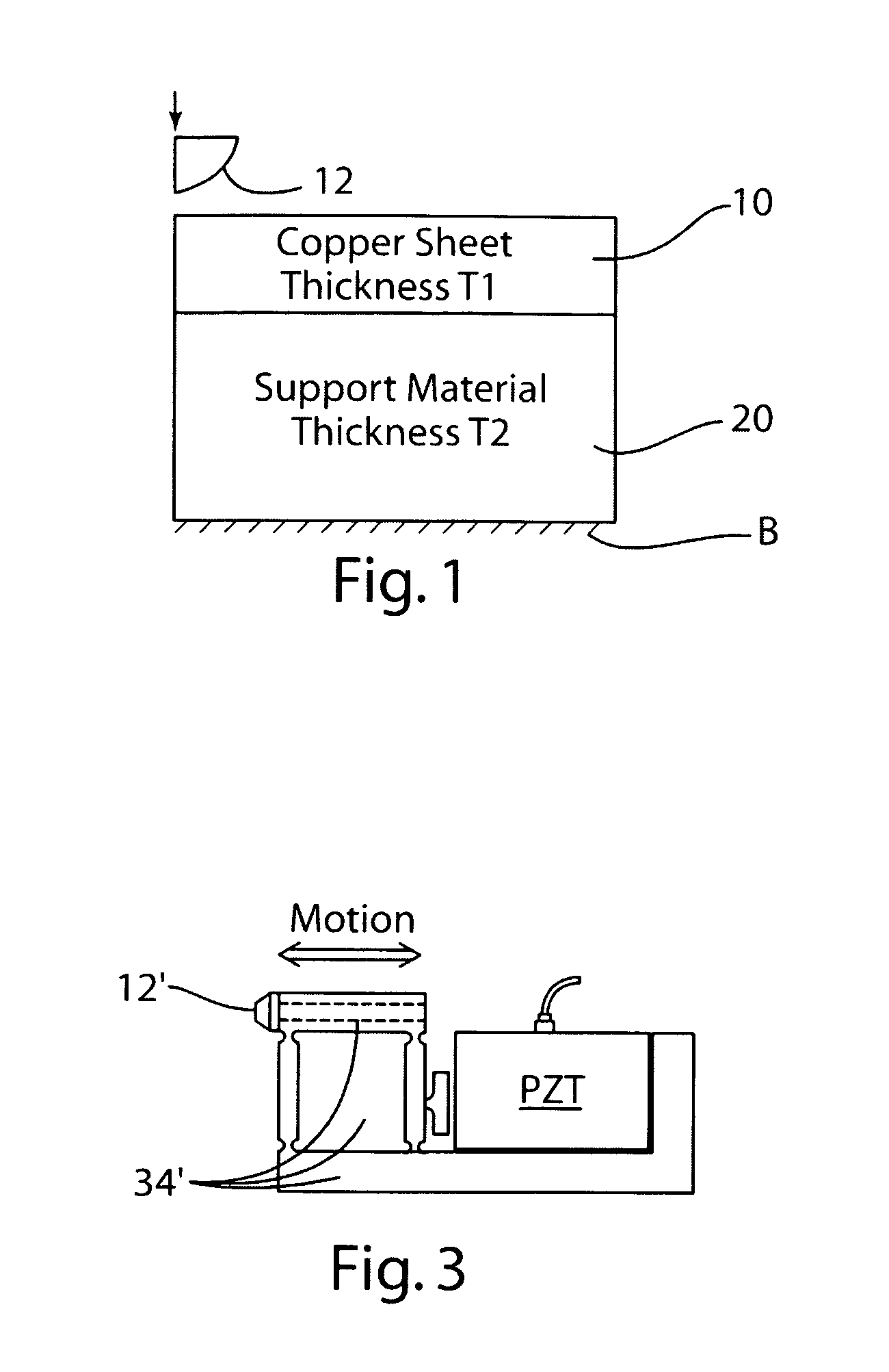
[0029]Arrays of micro-tool tips were used for the creation of surface texture in thin copper sheets. Hemispherical tool tips of diameter 300 μm were depressed into the copper sheet specimen approximately 150 μm in order to create cup-shaped depressions. A second, more flexible support layer was used underneath the copper sheet to serve as a support and to allow extensive deformation of the sheet material. The choice of the support layer material was dependent upon its ability to minimize bulging of the copper sheet. The thicknesses of the copper sheet and the support material could also be selected to minimize pile up (raised regions) of displaced copper sheet material at the edges of the dimple. To simulate the process, the problem was modeled as a two-dimensional symmetric punching process as illustrated in FIG. 1. The three design variables for the optimization problem were the support layer material (m), the thickness of the copper sheet (TI), an...


PUM

PropertyMeasurementUnit
depthaaaaaaaaaa
thicknessaaaaaaaaaa
heightaaaaaaaaaa

Abstract

Method of forming depressions (e.g. dimples) in a sheet material to form a textured surface thereon involves pressing one or more tool tips into a metallic or non-metallic sheet material while the sheet material is supported by a support layer that is relatively softer (e.g. having a lower Young's modulus) than the sheet material so as to allow plastic deformation and reduce pile-up of raised displaced material of the sheet material at the edges of the depressions.

Description

[0001]This application claims priority and benefits of U.S. provisional application Ser. No. 61 / 195,442 filed Oct. 7, 2008, the disclosure of which is incorporated herein by reference.FIELD OF THE INVENTION[0002]This invention relates to method and apparatus for rapidly and accurately creating micro-textured surfaces on sheet material using one or more tool tips pressed into the sheet material.BACKGROUND OF THE INVENTION[0003]Currently, surface texturing is done via machining, embossing, chemical etching, or laser ablation. Machining entails removal of material from a substrate to leave a desired geometry. One example surface texture creation by micro-machining is the use of a turning operation along with a micro-positioning system [1]. This method allows for accurate shapes and tolerances, but is fairly time consuming and expensive. It could also results in an undesirable residual stress in the workpiece.[0004]Embossing techniques use dies to plastically deform the surface of the m...

Claims


Application Information

Patent Timeline
Patent Type & Authority Patents(United States)
IPC IPC(8): B21J11/00B21D5/06B21B27/06
CPCB29C59/022Y10T428/12389Y10T428/24479B29C2059/023
Inventor CAO, JIANSWANSON, ANTHONYDAVIS, TIFFANY
Owner NORTHWESTERN UNIV
Why Eureka
Try Eureka