Surgical stapling instrument

a surgical and stapling technology, applied in the field of surgical stapling instruments, can solve the problems of limiting the use of staplers, unable to retract the instruments from the site of operation, and encountering limits in the application of wavy circular staplers, so as to increase the gradient of tissue flexure, increase the total extension, and increase the length of stapled seams

Inactive Publication Date: 2013-04-09
ETHICON ENDO SURGERY INC
View PDF20 Cites 1331 Cited by
  • Summary
  • Abstract
  • Description
  • Claims
  • Application Information

AI Technical Summary

Benefits of technology

[0015]Hence, the tissue interfaces of the surgical stapling instrument have a greater total extension than comparable planar or smooth wavy tissue interfaces. The particular shape with two opposite peaks and two opposite valleys angularly spaced at about 90° from the adjacent peaks consents to obtain an increased length of the stapled seam compared to traditional circular staplers without unnecessarily increasing the gradient of tissue flexure and the total longitudinal extension of the anastomosis along the lumen, thereby reducing the risk of trauma and tissue rupture. The length of the stapled seam is further increased by the locally stepped or offset surface configuration of the cartridge end surface and the staple forming surface which “oscillates” about the two-peaks-two-valleys wavy sha

Problems solved by technology

Although the use of the known surgical stapling instruments is very beneficial and greatly facilitates the performance of an anastomosis, it involves some problems.
Often it is difficult to retract the instrument from the site of the operation, because it is difficult to withdraw the anvil through the anastomotic opening defined by the closed row of staples, which is somewhat stiff.
Moreover, due to the oblique orientation of the staple driving direction with respect to the anvil approximation direction (axial direction of the stapler) the alignment of the staple-forming grooves at the anvil and the staple guide slots of the cartridge device varies undesirably with any variation of the distance between the cartridge device

Method used


Image

  • Surgical stapling instrument
  • Surgical stapling instrument
  • Surgical stapling instrument

Examples


Embodiment Construction

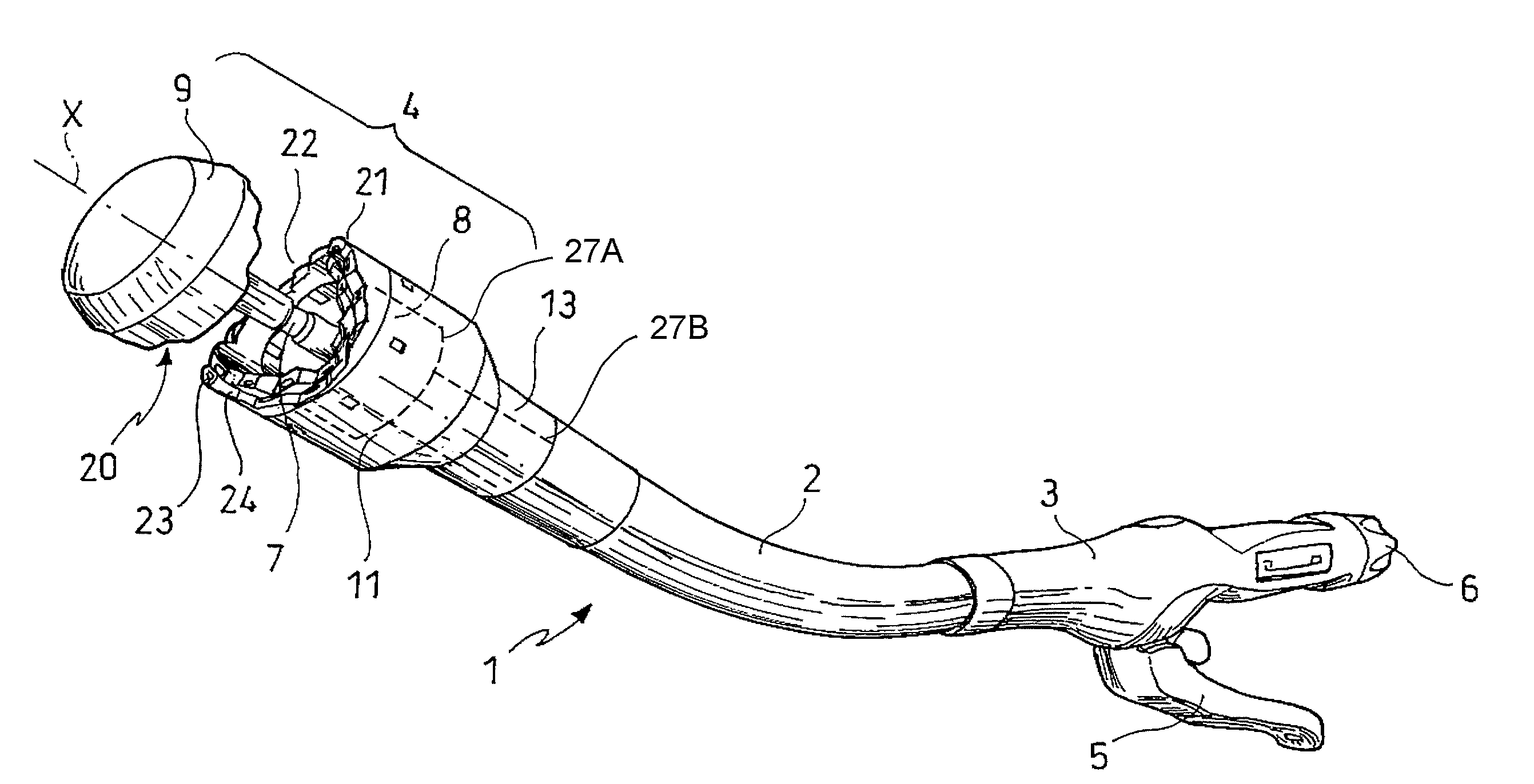
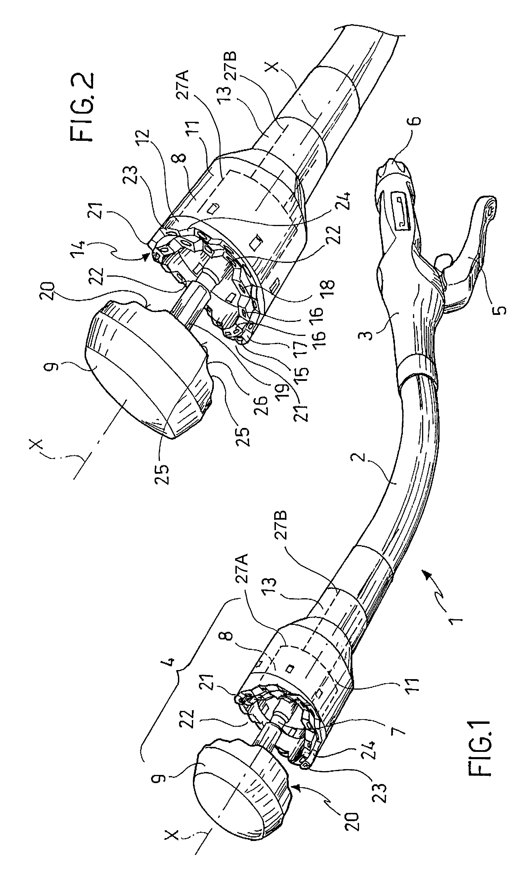
[0030]Turning to the figures, FIG. 1 shows an intraluminal surgical stapling instrument 1. The stapling instrument 1 comprises a frame having a body portion including a curved or straight shaft 2 and a handle 3. A staple fastening assembly 4 is preferably detachably mounted at the distal end of the shaft 2, in order to allow for removal of the staple fastening assembly from the shaft 2 and for replacement by another one, if desired.

[0031]An actuator trigger 5 is located in the proximal region of the stapling instrument 1. It can be swivelled towards handle 3 in order to “fire” the stapling instrument 1, i.e. for operating the staple driving device and the knife actuating device 27B of the internal mechanism of the stapling instrument. A rotatable adjusting knob 6 is provided for axially shifting a trocar shaft 7, in order to open or close the staple fastening assembly 4, i.e. in order to move the anvil of the stapling instrument 1.

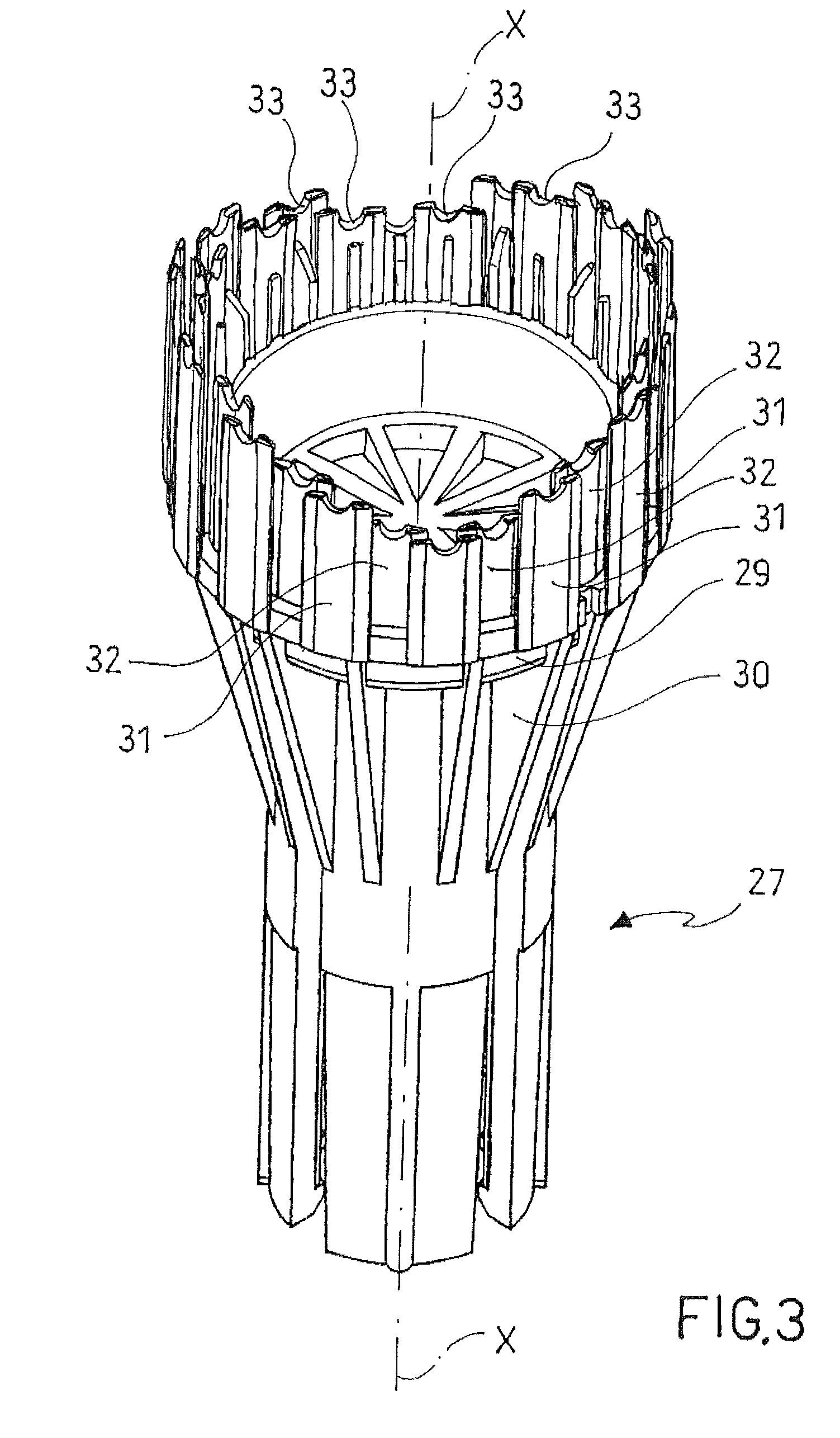
[0032]The staple fastening assembly 4 includes a car...


PUM

PropertyMeasurementUnit
Angleaaaaaaaaaa
Distanceaaaaaaaaaa
Lengthaaaaaaaaaa

Abstract

A surgical stapling instrument (1) comprises a staple fastening assembly (4) in the distal region of said instrument, the staple fastening assembly (4) including a cartridge device (8) which comprises at least one closed row (17, 18) of staples and defines a wavy distal end surface (14), and an anvil (9) which defines a wavy proximal staple forming surface (20) substantially matching the distal end surface (14) and which is adapted to cooperate with the cartridge device (8) for forming the ends of the staples exiting from the cartridge device (8), wherein the distal end surface (14) and the staple forming surface (20) have a globally wavy shape including two opposite peaks (21) and two opposite valleys (22) angularly spaced at about 90° from the adjacent peaks (21) and in that said two-peaks-two-valleys wavy shape is formed by a stepped configuration of said surfaces (14, 20).

Description

BACKGROUND OF THE INVENTION[0001]The invention relates to a surgical stapling instrument, which can be used for applying surgical staples or clips to tissue. And particularly the invention relates to an intraluminal surgical stapling instrument for the creation of an anastomosis.[0002]Surgical stapling is known in the art as a quick and efficient way of joining and repairing tissue and has become not only an acceptable but a preferred alternative to suturing.[0003]The known intraluminal surgical stapling instruments typically comprise an elongate shaft having a proximal actuating mechanism and a distal staple fastening assembly mounted to the shaft. The staple fastening assembly typically comprises a staple cartridge device containing a plurality of staples arranged in a circular closed array. A circular cutting knife having a closed cutting edge is contained within the cartridge device and is positioned such that there is at least one closed row of staples on the outside of the cut...

Claims


Application Information

Patent Timeline
IPC IPC(8): A61B17/115
CPCA61B17/1114A61B17/115A61B17/32053A61B17/068A61B17/105
Inventor PASTORELLI, ALESSANDROMURRAY, MICHAEL A.WEISENBURGH, II, WILLIAM BRUCEBILOTTI, FEDERICOCSIKY, LASZLOOMAITS, TODD PHILLIP
Owner ETHICON ENDO SURGERY INC
Why Eureka
Try Eureka