Vehicle lighting device

a technology for lighting devices and vehicles, applied in lighting and heating apparatus, lighting support devices, fixed installations, etc., can solve the problems of affecting light distribution performance, distorting the projecting lens, etc., and achieve the effect of reducing the thermal effect, reducing the temperature difference from the periphery of the light source, and efficient radiation

Inactive Publication Date: 2013-04-09
ICHIKOH IND LTD
View PDF4 Cites 24 Cited by
  • Summary
  • Abstract
  • Description
  • Claims
  • Application Information

AI Technical Summary

Benefits of technology

[0076]According to the present invention, a heat of which a temperature has risen at the periphery of a projecting lens is also well thermally transmitted from a lens holder integrally molded with a heat sink member to the heat sink member, and is efficiently radiated by means of the heat sink member, so that a temperature difference from the periphery of a light source can be substantially eliminated.
[0077]As a result, temperature regulation at the periphery of the projecting lens can be thoroughly performed, a conventional slight displacement between the projecting lens and the light source and a reflector due to a thermal effect never arises, and the lowering of light distribution performance due to the thermal effect can be avoided
[0078]In addition, even in a case where the projecting lens is a synthetic resin lens, the heat at the periphery of the projecting lens can be efficiently radiated by means of the heat sink member, as described previously, so that an occurrence of distortion due to the thermal effect of the projecting lens can be avoided.
[0079]Further, the projecting lens is held and fixed by a lens holder integrally molded with the heat sink member, so that a displacement due to an error of assembling between the projecting lens and the light source and the reflector can also be avoided, thus making it possible to improve light distribution performance in combination with the heat radiation effect described previously.

Problems solved by technology

In a case where this synthetic resin lens is employed as a projecting lens, distortion may occur to the projecting lens due to the aforementioned thermal effect.
Thus, if the lens holder portion is slightly deformed due to the thermal effect at the periphery of the projecting lens, or alternatively, if slight distortion occurs to the projecting lens itself, slight aberration occurs to an optical design between the projecting lens and the light source and the reflector, adversely affecting light distribution performance.

Method used


Image

  • Vehicle lighting device
  • Vehicle lighting device
  • Vehicle lighting device

Examples


Embodiment Construction

[0085]Hereinafter, taking an example of a vehicle headlamp, one embodiment of the present invention will be described in detail referring to the drawings.

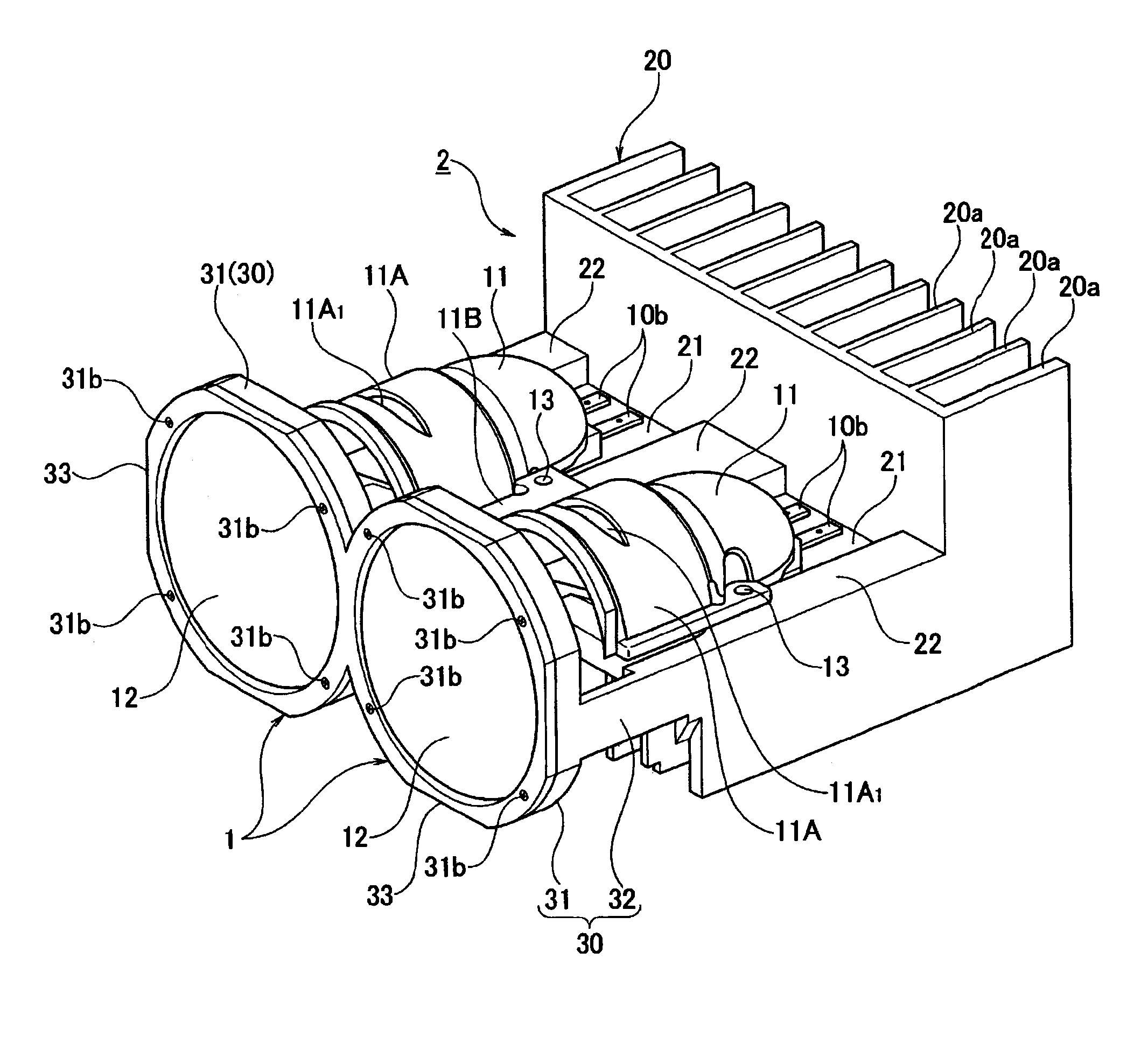
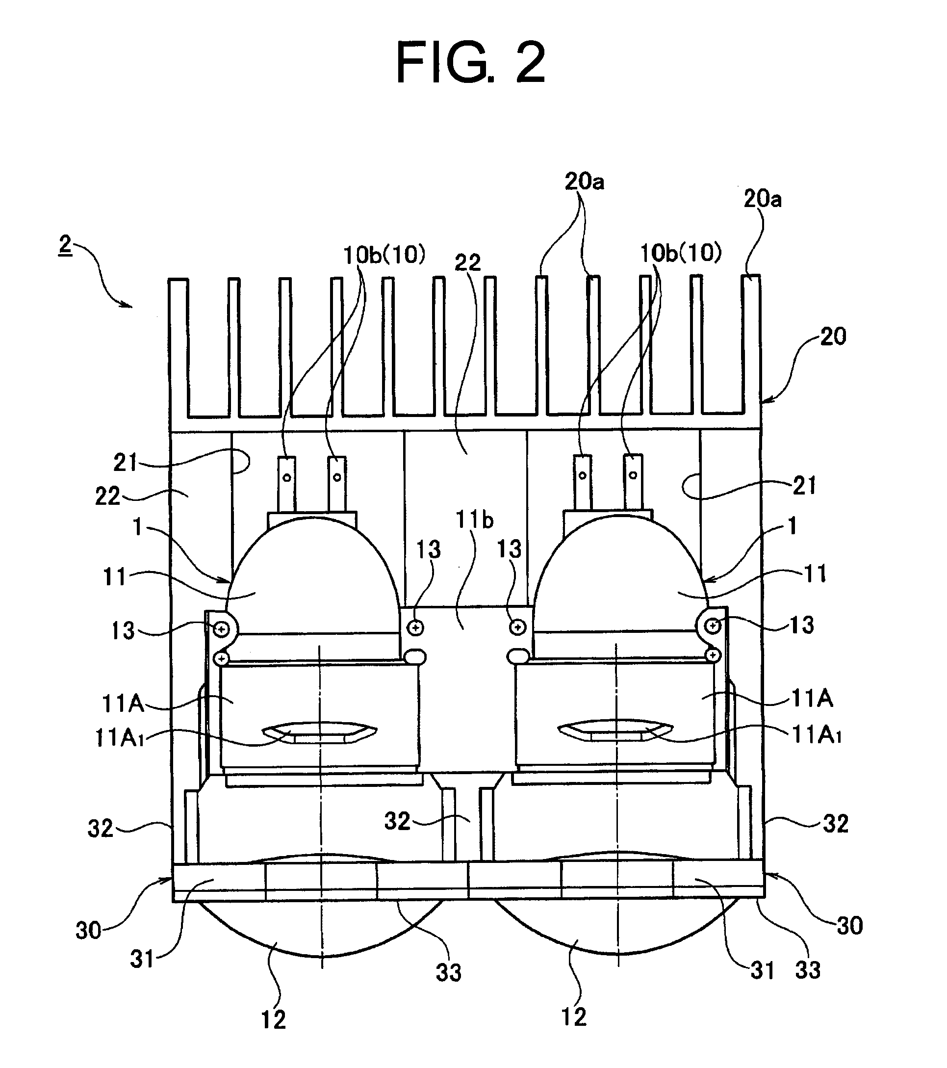
[0086]FIG. 1 is a perspective view showing a lighting unit in a headlamp, according to one embodiment of the present invention; FIG. 2 is a plan view of the lighting unit shown in FIG. 1; FIG. 3 is a side view of the lighting unit shown in FIG. 1; FIG. 4 is a front view of the lighting unit shown in FIG. 1; and FIG. 5 is a sectional view taken along the line A-A of FIG. 4.

[0087]The lighting unit in the headlamp, shown in FIGS. 1 to 5, is constituted as a projector-type lighting unit using a semiconductor-type light source as a light source. This lighting unit is provided with: a semiconductor-type light source 10; a reflector 11 having a concaved reflecting surface 11 a for reflecting a part of the light emitted from the semiconductor-type light source 10; a projecting lens 12 for focusing the direct light from the semiconductor-ty...


PUM


Abstract

A periphery of a projecting lens is heated due to radiation heat exerted by light emitted from a light source, like peripheries of the light source and a reflector. However, a lens holder holding the projecting lens is integrally molded with a heat sink member, so that a heat at the periphery of the projecting lens is well transmitted to the heat sink member by means of the lens holder, and is efficiently radiated by means of the heat sink member.

Description

CROSS-REFERENCE TO RELATED APPLICATIONS[0001]This application claims priority of Japanese Patent Application No. 2008-243718 filed on Sep. 24, 2008. The contents of this application are incorporated herein by reference in their entirety.BACKGROUND OF THE INVENTION[0002]1. Field of the Invention[0003]The present invention relates to a vehicle lighting device employed in a rear combination lamp or a fog lamp, etc., including an automobile headlamp, and in particular, to a projector-type vehicle lighting device in which direct light from a light source and light reflected by a reflector are focused by means of a projecting lens, and are radiated to the forward direction of a vehicle.[0004]2. Description of the Related Art[0005]Conventionally, as disclosed in Japanese Laid-open Patent Application No. 2007-109613, a projector-type vehicle lighting device is known as the one that constitutes a light source unit by integrally molding a lens holder for holding and fixing a projecting lens a...

Claims


Application Information

Patent Timeline
Patent Type & Authority Patents(United States)
IPC IPC(8): F21V21/00
CPCB60Q1/2696F21S48/1159F21S48/1163F21V29/763F21S48/1258F21S48/328F21V29/004F21S48/1216F21S41/148F21S41/155F21S41/255F21S41/295F21S45/48
Inventor KAWAMURA, TAKAYUKI
Owner ICHIKOH IND LTD
Why Eureka
Try Eureka