
Method and apparatus for characterizing a sample with two or more optical traps

a technology of optical traps and optical traps, applied in scanning probe microscopy, lasers, instruments, etc., can solve problems such as inability to characterize samples with two or more optical traps, and achieve the effect of avoiding interference with measurement data

Active Publication Date: 2013-04-09
BRUKER NANO INC +1
View PDF3 Cites 25 Cited by
  • Summary
  • Abstract
  • Description
  • Claims
  • Application Information

AI Technical Summary

Benefits of technology

The patent describes a method for measuring the position of a probe on a sample using two optical traps. The method involves correlating the measurement data from the two traps to correct any errors caused by the interaction between the sample and the traps. The measurements are carried out at the same location in a short period of time, which helps to eliminate errors caused by movement of the sample. The method also allows for the use of movable detectors to track a movable signal and achieve higher sensitivity and measuring range.

Problems solved by technology

As discussed in connection with the prior art, there will inevitably be interferences in the measurement data as a result of the interaction between the light forming the optical trap and the sample.

Method used


Image

  • Method and apparatus for characterizing a sample with two or more optical traps
  • Method and apparatus for characterizing a sample with two or more optical traps
  • Method and apparatus for characterizing a sample with two or more optical traps

Examples


Embodiment Construction

[0036]The invention will be explained below by means of preferred embodiments in connection with the attached figures, wherein:

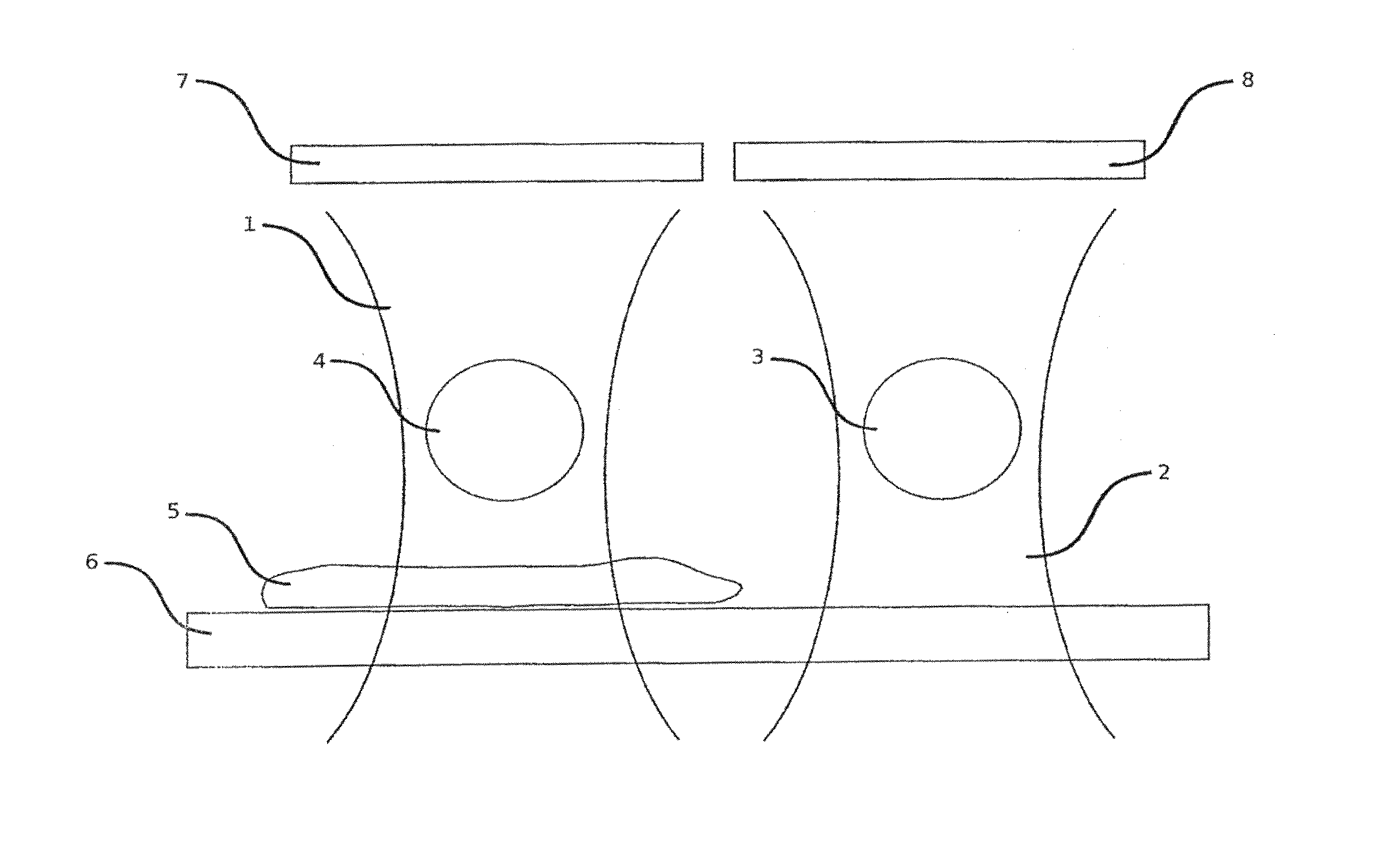
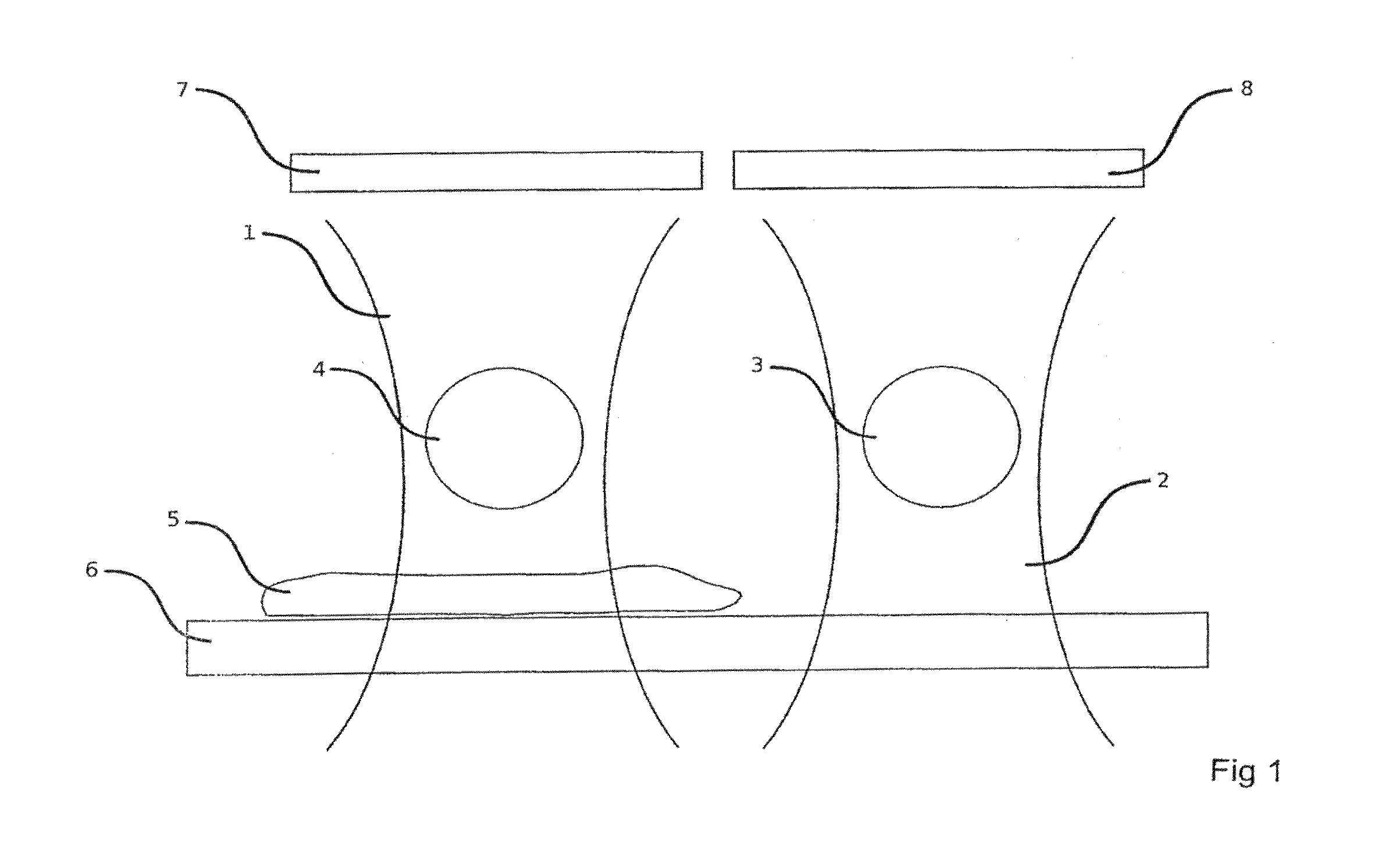
[0037]FIG. 1 shows a simplified illustration of two optical traps including a possible interference on the optical path;

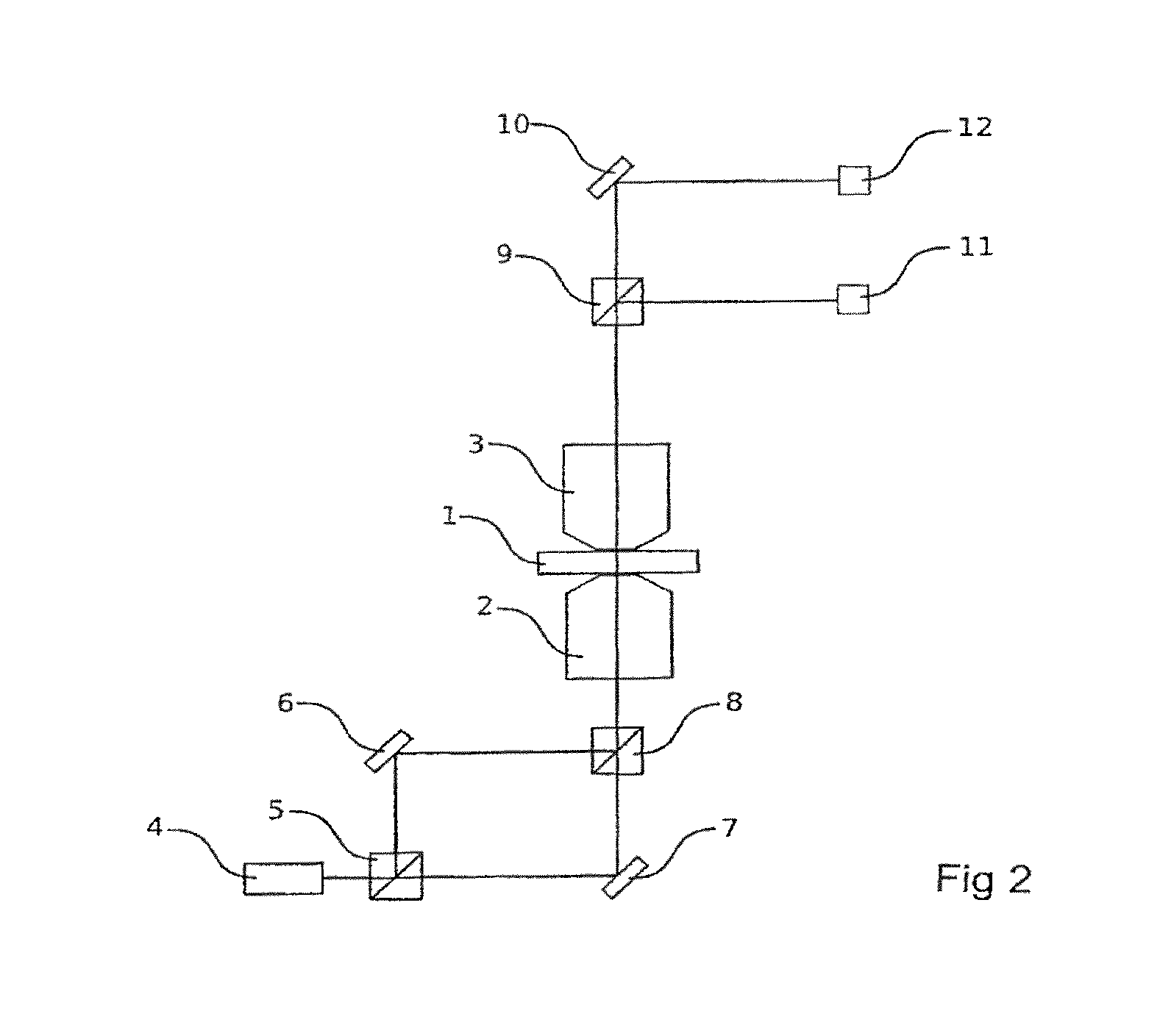
[0038]FIG. 2 shows a schematic diagram of the generation of two traps which distinguish themselves in the polarisation of the light and the separation of the signals of the two traps;

[0039]FIG. 3 shows a schematic diagram of the generation of two traps which distinguish themselves in the wavelength of the light and the separation of the signals of the two traps;

[0040]FIG. 4 shows a schematic diagram of the generation of two traps which distinguish themselves at least in their direction of propagation and the spatially separated detection of the two signals;

[0041]FIGS. 5a and b show a schematic diagram for possible coupled movements of two traps;

[0042]FIG. 6 shows a schematic diagram for possible coupled movements of two or more traps.

[0043]...


PUM


Abstract

The present invention relates to a method for investigating a sample using scanning probe photon microscopy or optical force microscopy, and to an apparatus which is designed accordingly. The method or the apparatus provides for two optical traps which can be moved in a local region of the sample, wherein in at least one of the two traps a probe is held. The sample is scanned using the two traps and the measured data from the two traps are captured separately and evaluated by correlation. In particular interference signals resulting from an interaction between sample and light trap can be eliminated by the method.

Description

CROSS-REFERENCE TO RELATED APPLICATION[0001]This is a submission pursuant to 35 U.S.C. 154(d)(4) to enter the national stage under 35 U.S.C. 371 for PCT / DE2008 / 000897 filed May 30, 2008. Priority is claimed under 35 U.S.C. 119(a) and 35 U.S.C. 365(b) to German Patent Application Numbers 10 2007 025534.0 tiled May 31, 2007, 10 2007 025533.2 filed May 31, 2007, 10 2007 025535.9 filed May 31, 2007, 10 2007 025532.4 filed May 31, 2007, 10 2007 063065.6 filed Dec. 21, 2007 and 10 2007 063066.4 filed Dec. 21, 2007. The subject matters of PCT / DE2008 / 000897 and German Patent Application Numbers 10 2007 025534.0, 10 2007 025533.2, 10 2007 025535.9, 10 2007 025532.4, 10 2007 063065.6 and 10 2007 063066.4 are hereby expressly incorporated herein by reference in their entirety.[0002]The invention relates to a method and an apparatus for measuring the properties of a sample by means of a scanning probe method, in particular by means of a “Photonic three microscope” (PFM).BACKGROUND OF THE INVENT...

Claims


Application Information

Patent Timeline
Patent Type & Authority Patents(United States)
IPC IPC(8): H01S1/00H01S3/00H05H3/02G01Q10/06G01Q30/06G01Q60/00
CPCB82Y35/00G01Q10/06G02B21/32G01Q60/00G01Q30/06
Inventor HEYN, SVEN-PETERKERSSEMAKERS, JACOBKNEBEL, DETLEFEGGERT, HELGEJAEHNKE, TORSTENKAMPS, JOERN
Owner BRUKER NANO INC
Learn More