Brushless motor

a brushless motor and motor body technology, applied in the direction of magnet circuit rotating parts, piston pumps, magnetic circuit shapes/forms/construction, etc., can solve the problems of difficult winding configuration, complicated winding configuration, and difficulty in assembling more coils, and achieve low cogging torque and simple winding structure.

Inactive Publication Date: 2013-04-09
JOHNSON ELECTRIC SA
View PDF8 Cites 10 Cited by
  • Summary
  • Abstract
  • Description
  • Claims
  • Application Information

AI Technical Summary

Benefits of technology

[0008]Hence there is a desire for a brushless direct current (BLDC) motor which has a simple winding structure with low cogging torque.

Problems solved by technology

However, with the advent of high alcohol fuels, chemical reactions between the commutator and the fuel has become problematic leading to the use of graphite commutators and renewed interest in brushless motors to drive the fuel pumps.
This is difficult to wind in small diameter motors.
The main problem with the existing stator geometry is that the winding configuration is complicated for small diameter, lower power applications, such as the automotive fuel pump, water pump and air pump, etc.
In these applications, the stator inner diameter is very small, just around 20 mm, therefore it is difficult to assemble more coils, especially for mass production.
Another problem with existing products is the high cogging torque, which creates noise and vibration.
This has restricted the use of BLDC motors in many fields which need low noise and low vibration.
From this figure we can see that the winding becomes even more complicated with three coils per phase and a lower efficiency caused by longer winding end-turns.
Another problem with existing products is that it is not suitable for overmold technology in the fuel pump application.
However, this results in the stator becoming a solid body, i.e., there is no space for fuel to pass through, except through the air gap between the rotor and the stator.
However, to maintain motor efficiency, the air gap is very small with the result that the fuel flow is insufficient.

Method used


Image

  • Brushless motor
  • Brushless motor
  • Brushless motor

Examples


Embodiment Construction

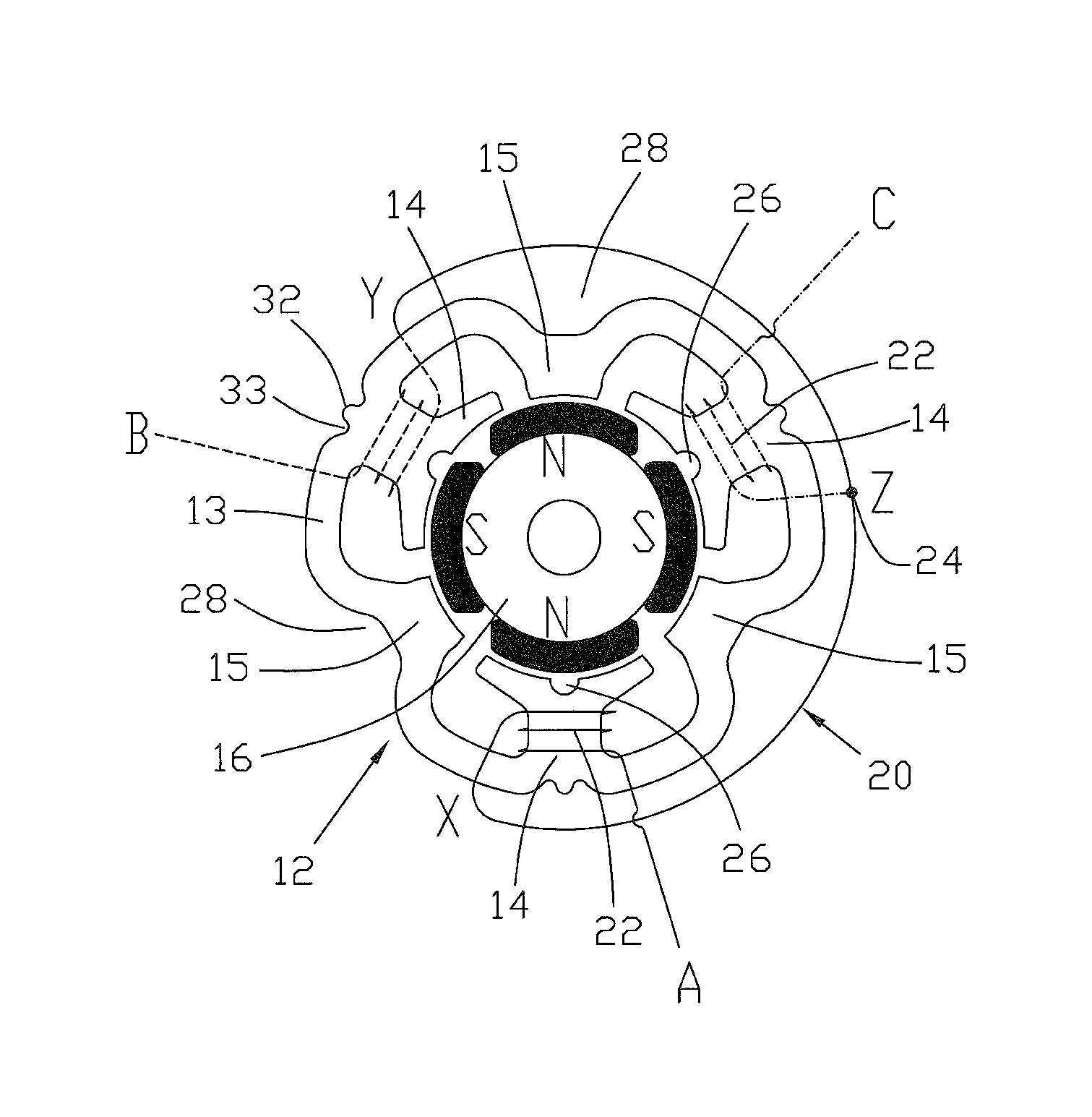
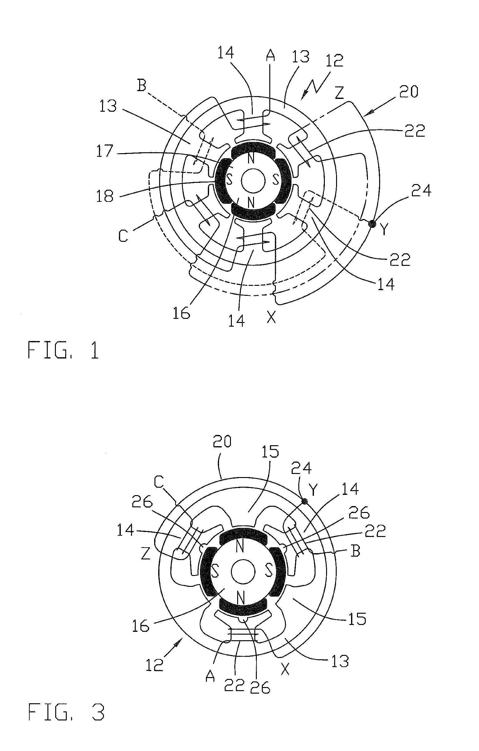
[0035]FIG. 3 is a schematic winding diagram for a 3-phase BLDC motor for a first preferred embodiment. The stator 12 has a stator core 13 with six teeth 14, 15 forming the stator poles as will be described later. The winding 20 has only three coils 22 formed about alternate teeth 14. The winding 20 is a 3-phase star winding having three legs, one leg for each phase, with one end A,B,C, of each leg being connected to the stator terminals (one for each phase) and the other end X,Y,Z, of each leg being connected together at 24 to form a star connection. Thus each leg has only one coil 22. This is easier to wind especially in small diameter motors. However, the wound teeth 14 have a larger circumferential extent than the unwound teeth 15 and have a deep groove 26 in the pole face which extends axially for the length of the tooth 14 and radially outwardly into the tooth, dividing the pole face into two, preferably equal, portions. The groove 26 has the effect of dividing the tooth 14 int...


PUM


Abstract

A brushless direct current (BLDC) motor has a 3-phase winding 20 and six stator teeth 14, 15 with alternate stator teeth 14 being wound and the remaining stator teeth 15 being left unwound. The winding 20 has three legs, one for each phase and each leg has one coil 22 wound about one of the stator teeth 14. Each leg has a first end A,B,C, arranged to receive electrical power and a second end X,Y,Z, which is connected to the second end of the other legs to form a star connection 24. Selected stator teeth have grooves in a face thereof dividing those teeth into a plurality of stator poles. The motor may be used to drive a fuel pump for an internal combustion engine, typically for a vehicle.

Description

CROSS REFERENCE TO RELATED APPLICATIONS[0001]This non-provisional patent application claims priority under 35 U.S.C. §119(a) from Patent Application No. 200810141852.7 filed in The People's Republic of China on Sep. 3, 2008.FIELD OF THE INVENTION[0002]This invention relates to a brushless motor and in particular, to a fuel pump having a brushless motor, especially a brushless direct current (BLDC) motor.BACKGROUND OF THE INVENTION[0003]Fuel pumps are used in motor vehicles to transfer liquid fuel, typically gasoline or diesel from a fuel tank to an internal combustion engine. The pump is driven by a small DC motor and to minimize fuel leakage through bearing seals etc, the fuel passes through the interior of the motor. This works very well even with motors having commutators, with the fuel cooling the motor and eliminating sparking between the brushes and the commutator. However, with the advent of high alcohol fuels, chemical reactions between the commutator and the fuel has become...

Claims


Application Information

Patent Timeline
Patent Type & Authority Patents(United States)
IPC IPC(8): H02K1/14H02K3/28
CPCH02K1/14H02K1/148H02K21/14H02K29/03
Inventor LI, YONG BINYUAN, WEI FENGSUN, NINGWANG, XIN PING
Owner JOHNSON ELECTRIC SA
Why Eureka
Try Eureka