
Sensory signal output apparatus

a sensory signal and output apparatus technology, applied in the direction of deaf-aid sets, electrical transducers, transducer details, etc., can solve the problems of increasing the total size of the sensory signal output apparatus, shortening the diameter of the magnetic circuit b>1/b>, and low workability and productivity, so as to improve the vibrating force and middle-low sound characteristics, facilitate coupling, and maximize weight

Inactive Publication Date: 2013-04-09
BUJEON
View PDF8 Cites 3 Cited by
  • Summary
  • Abstract
  • Description
  • Claims
  • Application Information

AI Technical Summary

Benefits of technology

[0015]In the present invention, an elastic support means is inserted into and coupled to a magnetic circuit without using a curling operation to provide easy coupling. Furthermore, the present invention may maximize a weight and the size of a magnet in a magnetic circuit having the same diameter and height to improve vibrating force and middle-low sound characteristics.

Problems solved by technology

However, because easy coupling is not achieved, there is a problem in that the workability and productivity are low.
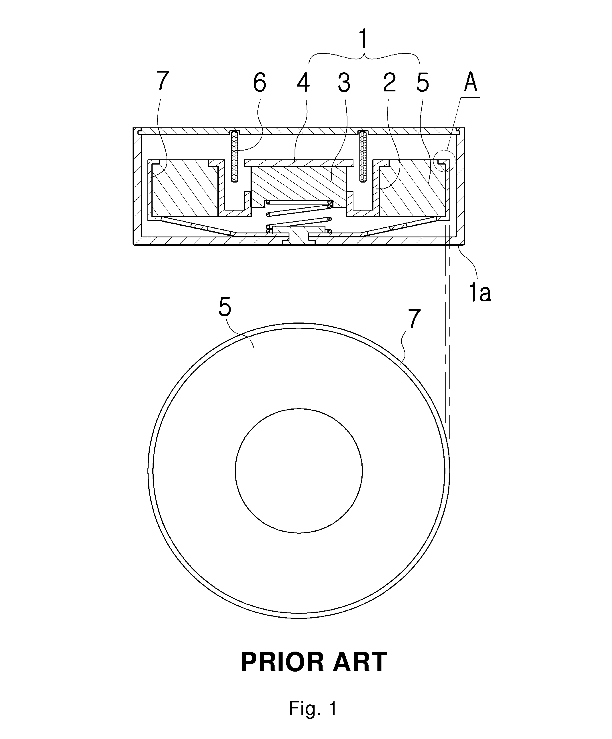
Further, in the conventional sensory signal output apparatus, because an annular end of the plate spring 7 surrounds and fixes the circumferential outer surface of the magnetic circuit 1, there is a problem in that a diameter of the magnetic circuit 1 become shorter corresponding to the thickness of the plate spring 7 to make a weight light.
This results in an increase of the total size of the sensory signal output apparatus, which runs counter to the miniaturized trend of electronic parts business being in the.
In this case, the small size (the size of small fingernail) cannot provide a weight associated with vibration easily.

Method used


Image

  • Sensory signal output apparatus
  • Sensory signal output apparatus
  • Sensory signal output apparatus

Examples


Embodiment Construction

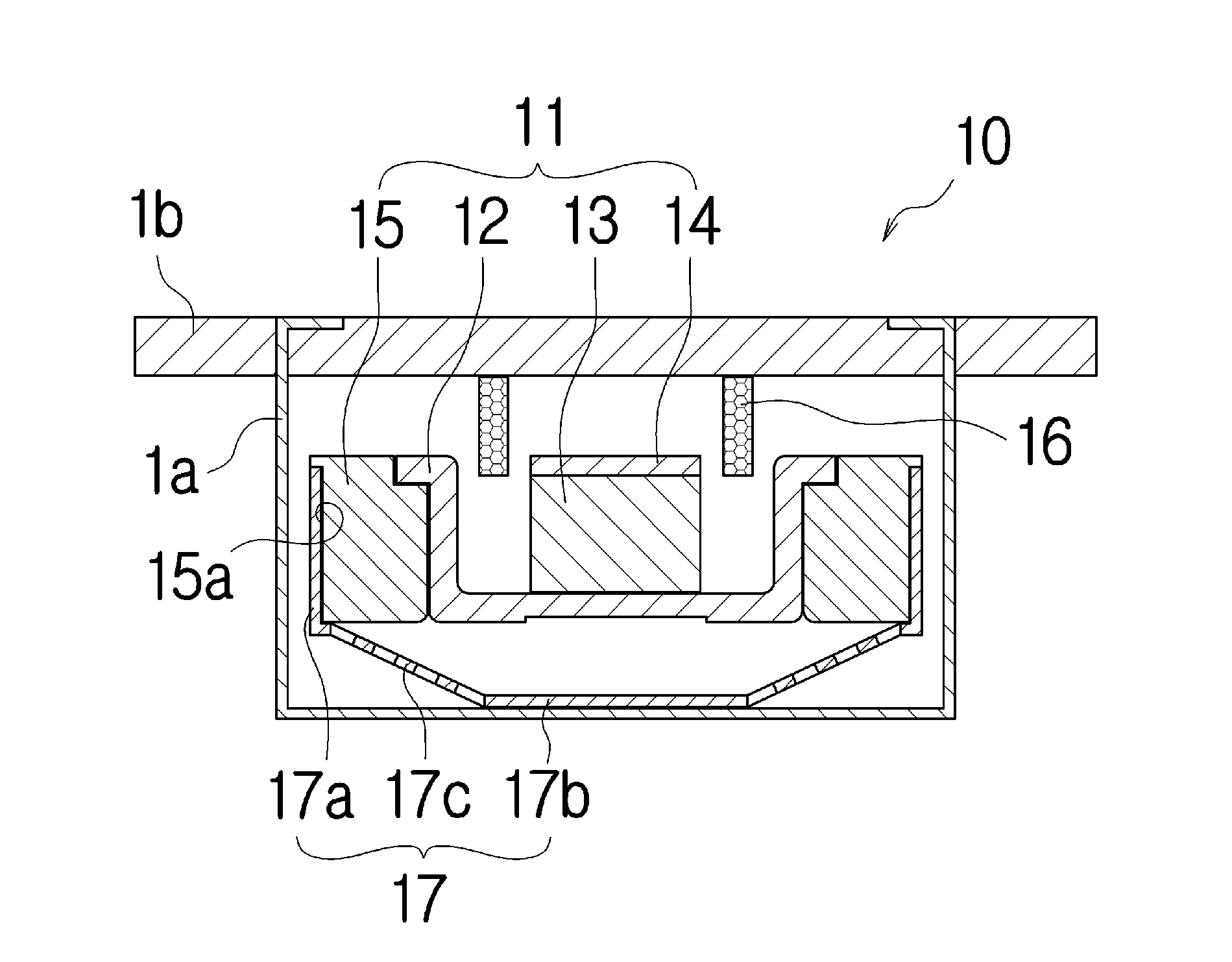
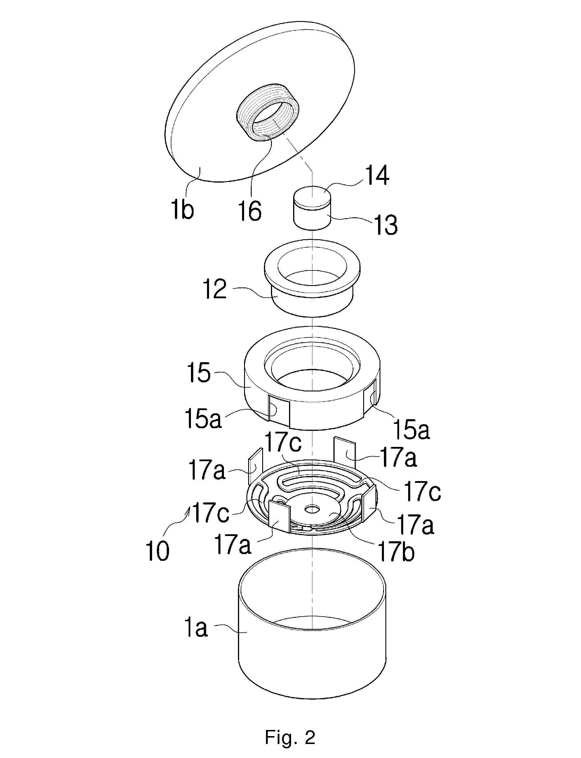
[0025]FIG. 2 is an exploded perspective view illustrating a configuration of a sensory signal output apparatus according to an embodiment of the present invention, FIG. 3 is a cross-sectional view illustrating the sensory signal output apparatus shown in FIG. 2, FIG. 4 is a cross-sectional view illustrating an example of a coupling structure of a magnetic circuit and an elastic support means according to an embodiment of the present invention, FIGS. 5 and 6 are cross-sectional views illustrating other examples of a coupling structure of a magnetic circuit and an elastic support means according to an embodiment of the present invention, FIG. 7 is an exploded perspective view illustrating a coupled state of a magnetic circuit and an elastic support means according to an embodiment of the present invention, FIG. 8 is a plan view illustrating a confirmed state in a volume of a weight member according to an embodiment of the present invention, and FIGS. 9 and 10 are views illustrating ex...


PUM


Abstract

A sensory signal output apparatus is provided. The sensory signal output apparatus, includes: a magnetic circuit vibrating in response to an alternating signal flowing through a coil; and an elastic support means elastically supporting the magnetic circuit to surround the circumferential outer surface of the magnetic circuit from one side direction thereof, in which coupling recesses are formed at the circumferential outer surface of the magnetic circuit to be spaced apart from each other, and a coupling piece is provided at a periphery of the elastic support means to be coupled to the coupling recess, the coupling piece is attached to and inserted into the coupling recess. In the sensory signal output apparatus, an elastic support means is inserted into and coupled to a magnetic circuit without using a curling operation to provide easy coupling.

Description

BACKGROUND OF THE INVENTION[0001]1. Field of the Invention[0002]The present invention relates to a sensory signal output apparatus for outputting vibration, sounds, or both of them.[0003]2. Description of the Related Art[0004]As well known to those skilled in the art, a sensory signal output apparatus is an apparatus outputting voices or vibrating force such as a speaker, a receiver, a buzzer, or vibrator which converts an electric signal, input from a signal source, into a mechanical signal to output sounds or generate vibration.[0005]As shown in FIG. 1, in a conventional sensory signal output apparatus, the magnetic circuit 1 a magnetic circuit 1 including a yoke 2, a magnet 3, and a top plate 4 responds to a magnetic flux formed at an aperture depending on a direction of an alternating signal input to a coil 6 located at an opening between the yoke 2, the magnet 3, and the top plate 4, and vibrates to generate vibrating force and / or sounds. In this case, the magnet 3 and the top ...

Claims


Application Information

Patent Timeline
Patent Type & Authority Patents(United States)
IPC IPC(8): H04R25/00
CPCH04R11/02H04R2400/07H04R9/02H04R9/06
Inventor KANG, YUN GYU
Owner BUJEON
Learn More