Reciprocating workpiece device with a drive system seeking the resonance of the driven system portion thereof

a technology of drive system and workpiece, which is applied in the direction of asynchronous induction clutch/brake, carpet cleaner, asynchronous induction clutch/brake, etc., can solve the problems of increasing costs, increasing costs, and raising quality control problems, and achieves the effect of effective workpiece action

Active Publication Date: 2013-04-16
KONINKLIJKE PHILIPS ELECTRONICS NV
View PDF12 Cites 73 Cited by
  • Summary
  • Abstract
  • Description
  • Claims
  • Application Information

AI Technical Summary

Benefits of technology

[0006]Accordingly, the present invention is a workpiece system having a reciprocating action, comprising: a drive assembly producing an output drive signal comprising periodic force pulses, resulting in a drive frequency which increases from zero in operation of the drive assembly; and a driven member assembly having a workpiece mounted thereon with a return spring assembly, the driven member assembly having a resonant frequency, wherein, as the drive frequency increases from zero, it will approach the resonant frequency of the driven assembly, wherein at approximately said resonant frequency, at least a substantial portion of energy produced by the motor assembly is transferred into the movement of the workpiece, producing an effective workpiece action.

Problems solved by technology

Tuning of the devices during assembly, or by using an adaptive drive system, is necessary but is typically tedious and expensive, increasing costs and raising quality control issues.
Non-resonant systems, on the other hand, usually have problems of efficiency at relatively high operating speeds, as well as high noise levels, due to the normal operation of the drive train portion of such systems.

Method used


Image

  • Reciprocating workpiece device with a drive system seeking the resonance of the driven system portion thereof
  • Reciprocating workpiece device with a drive system seeking the resonance of the driven system portion thereof
  • Reciprocating workpiece device with a drive system seeking the resonance of the driven system portion thereof

Examples


Embodiment Construction

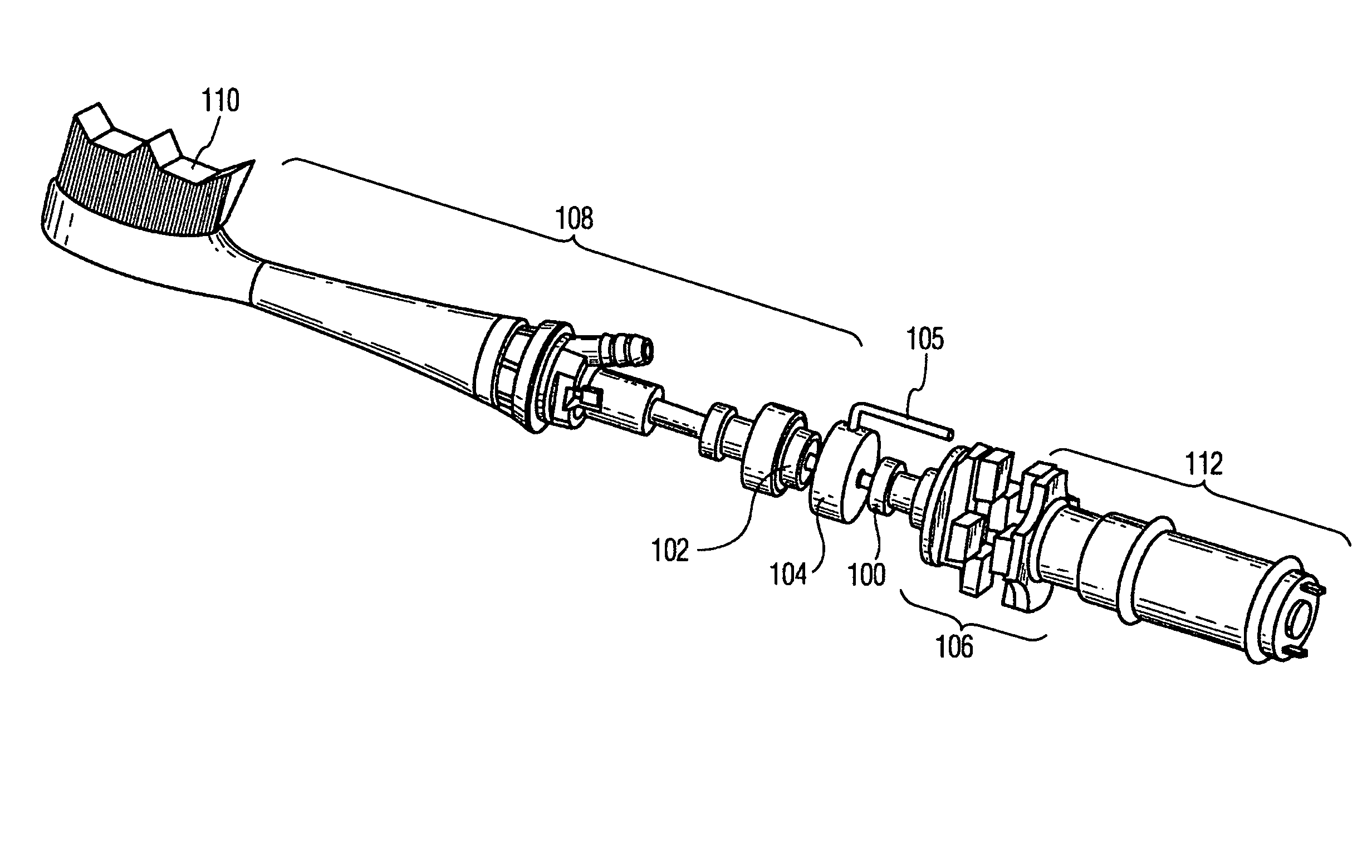
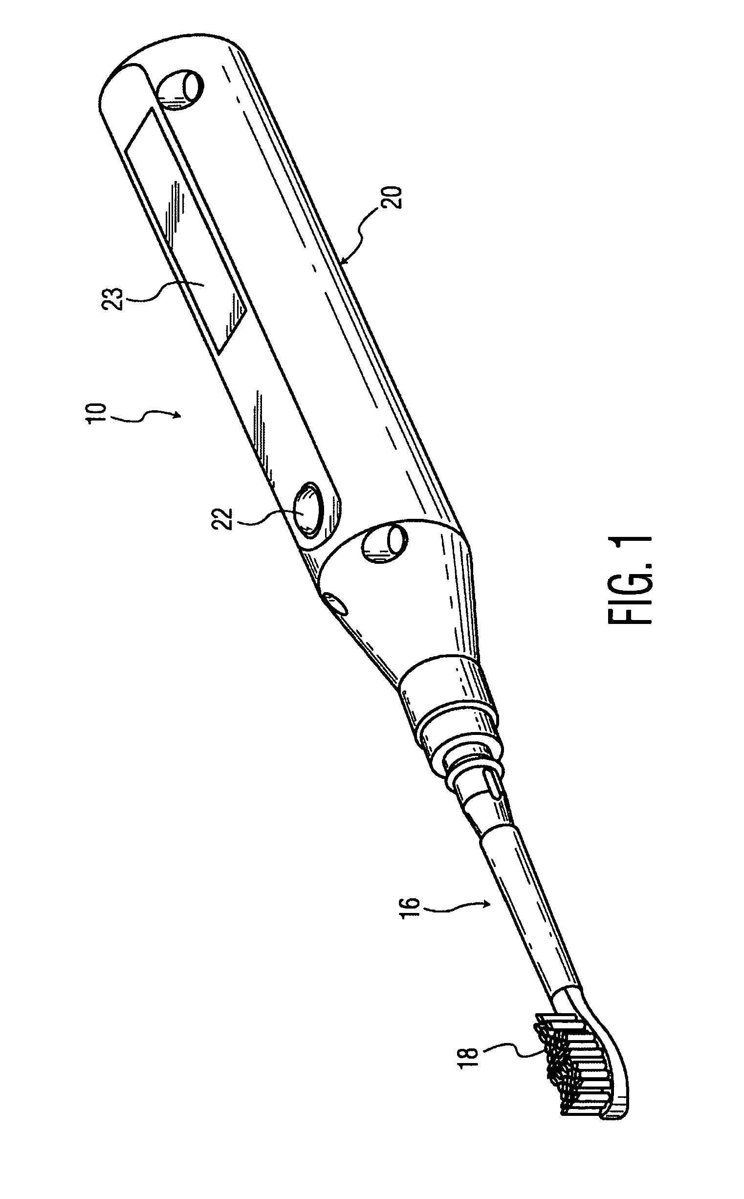
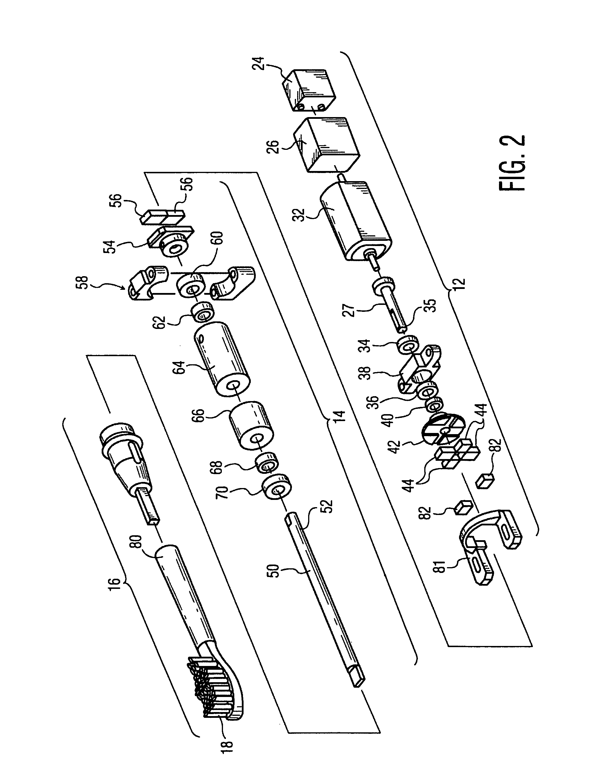
[0014]Referring to FIGS. 1 and 2, an embodiment of the invention shown and described herein includes a toothbrush 10 with drive assembly 12 which could, for instance, include a DC motor, and a driven assembly 14, the drive assembly 12 and the driven assembly 14 being coupled by a magnetic coupling arrangement, a portion of which is in the drive assembly 12 and a portion of which is in the driven assembly 14. At the remote (outboard) end of driven assembly 14 is a workpiece assembly 16, which as an example could include a toothbrush 18, but which could include a large number of other workpieces which have a reciprocating motion.

[0015]The drive assembly 12 and driven assembly 14 in the embodiment shown are positioned in a hand-held housing 20, which includes an on / off button 22 and could include a display 23 for providing a visual representation of various operating aspects of the device. The drive assembly 12, shown in detail in FIG. 2, is powered by a battery 24 and a power control ...


PUM


Abstract

A workpiece system with a reciprocating motion which includes a motor assembly for producing an output drive signal with a periodic force pulse. The drive signal is coupled to a driven member assembly through a magnetic arrangement, wherein the driven member assembly has a workpiece mounted thereon with a return spring assembly. The driven member assembly has a resonant mechanical frequency. As the RPM of the motor increases from zero following startup, the drive signal frequency increases to the point very near resonance, where the energy from the drive signal is transferred into the reciprocating motion of the driven assembly, producing an effective amplitude of workpiece motion.

Description

CROSS REFERENCE TO RELATED APPLICATION[0001]This application claims the benefit of U.S. provisional application Ser. No. 60 / 695,659 filed Jun. 30, 2005, which is incorporated herein by reference.TECHNICAL FIELD[0002]This invention relates generally to power devices having a reciprocating workpiece, such as a power toothbrush, which operate at or near resonance, and more particularly concerns such a device which includes a drive system which seeks the resonant frequency of an associated reciprocating driven system.BACKGROUND OF THE INVENTION[0003]Resonant operation is useful and desirable for power devices having workpieces with reciprocating motion, due to the inherent efficiency of such devices when they are operating at or near resonance. In such a case, the driven assembly / system portion of the device which includes the workpiece is driven at or near its resonant frequency. This requires matching substantially the drive frequency of the drive system portion of the device to the r...

Claims


Application Information

Patent Timeline
Patent Type & Authority Patents(United States)
IPC IPC(8): A61C17/34
CPCA61C1/07A61C17/34H02K7/06H02K49/108
Inventor MILLER, KEVIN A.PACE, JOHN W.BENNING, WOLTER F.HEADSTROM, PATRICK A.
Owner KONINKLIJKE PHILIPS ELECTRONICS NV
Why Eureka
Try Eureka