
Linear solar heat generating system

a solar heat generating system and linear technology, applied in the direction of mechanical equipment, machines/engines, light and heating equipment, etc., can solve the problems of lowering the efficiency of power generation, solar cells are expensive and significantly lower power generation efficiency, and are difficult to maintain and repair,

Inactive Publication Date: 2013-04-16
CHAE SOO JOH
View PDF14 Cites 2 Cited by
  • Summary
  • Abstract
  • Description
  • Claims
  • Application Information

AI Technical Summary

Benefits of technology

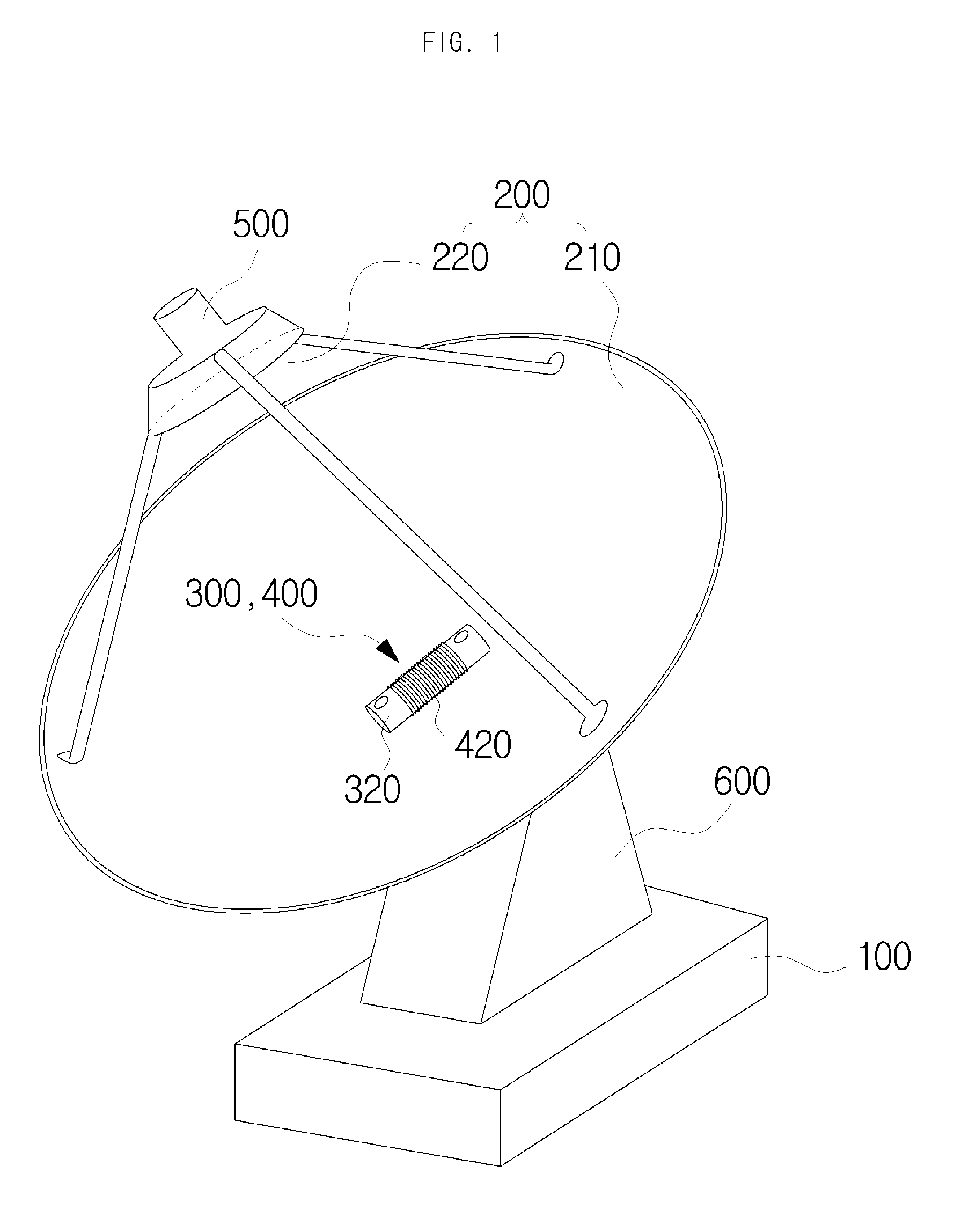
[0046]The linear solar heat generating system in accordance with the present invention allows for an easy installation, maintenance and repair, highly efficient power generation and eco-friendly power generation through the simple structure of integrating the linear power generator with the heat engine that linearly reciprocates the piston by thermal expansion and contraction of the high-pressure gas by alternately transferring the concentrated sunlight form the solar concentrator to the front and rear spaces of the cylinder.
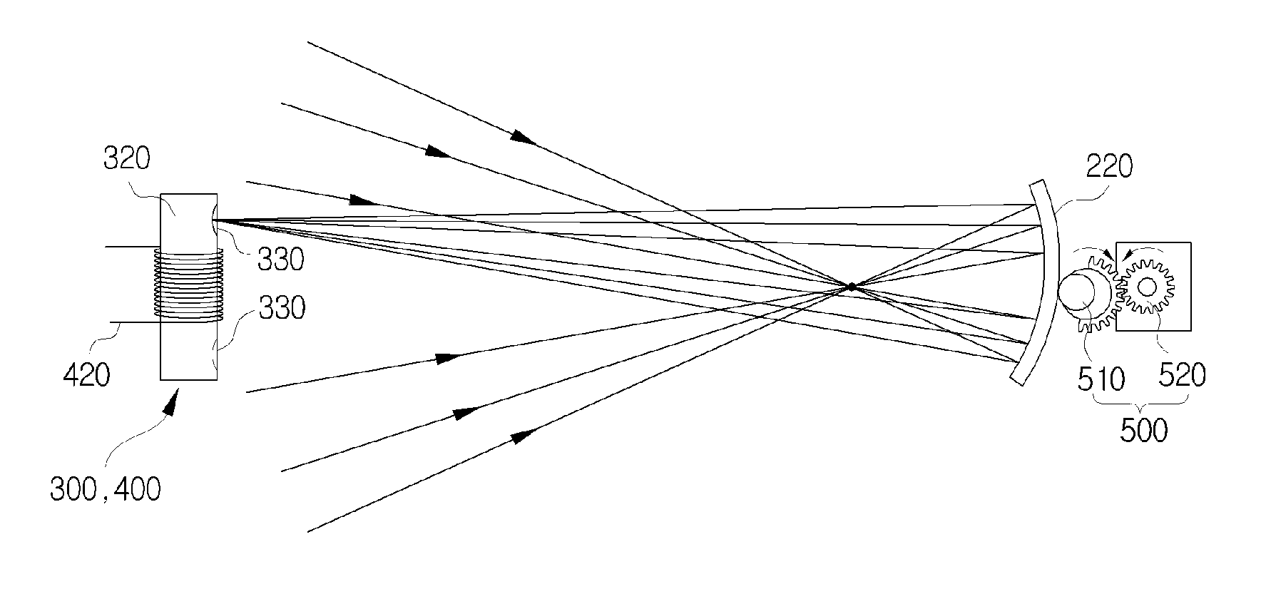
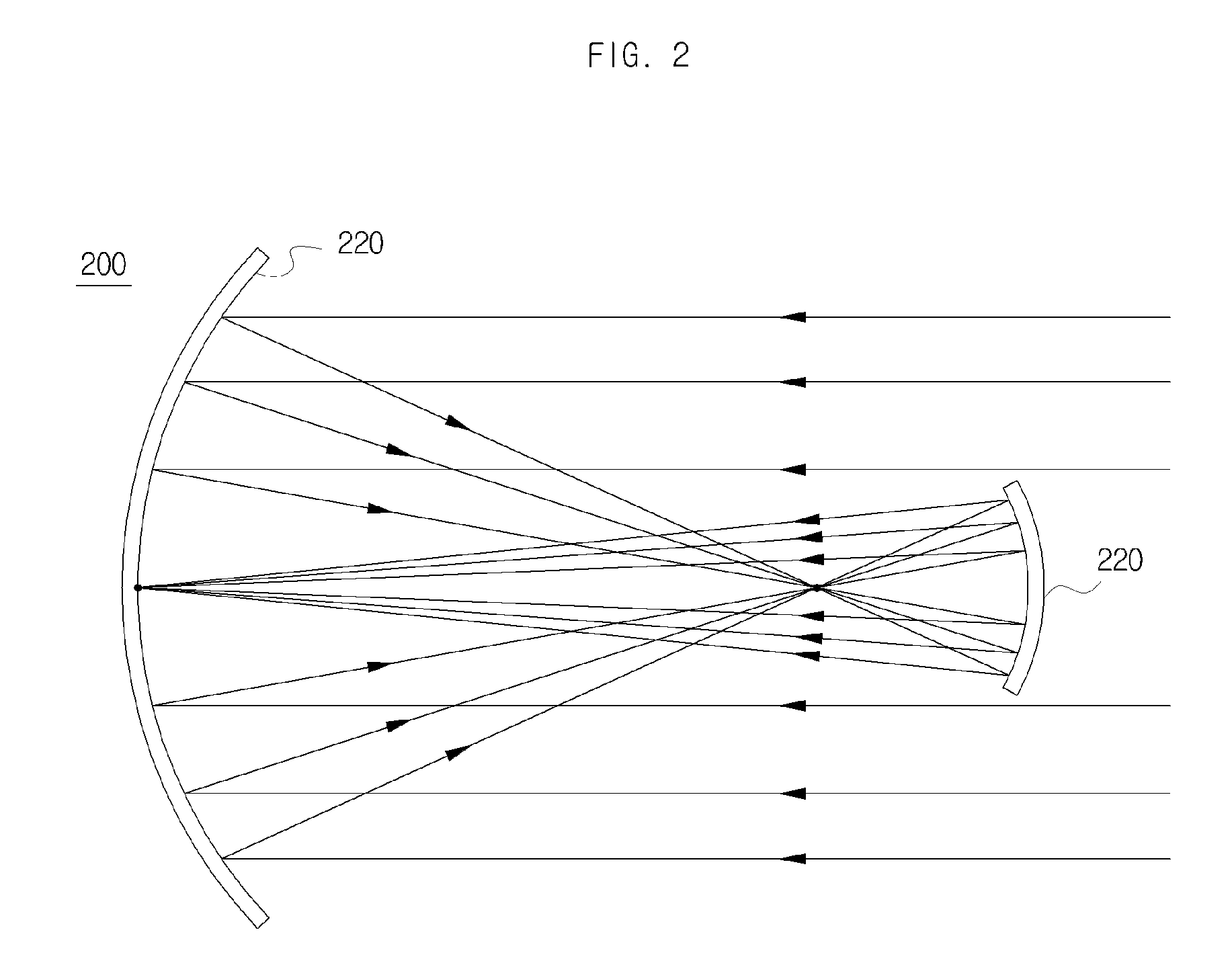
[0047]Moreover, by designing the solar concentrator as a Cassegrain type or a Gregorian type constituted with the primary mirror and the secondary mirror, the sunlight can be concentrated in a higher density, thereby enhancing the efficiency of thermal expansion of the high-pressure gas, and the cooling unit can enhance the cooling efficiency of the high-pressure gas inside the cylinder, thereby increasing the overall thermal efficiency and achieving high-efficient power generation.

Problems solved by technology

However, this solar cell uses only a portion of sunlight in the range of visible and infrared rays, and low energy photon in long wavelength infrared ray cannot be used for electricity generation but increase the temperature of the solar cells, thereby lowering the efficiency of power generation.
Moreover, the solar cells are expensive and have a significantly lower efficiency of power generation than the heat engines.
However, to drive the generator by operating such turbine or Stirling engine, the overall equipment becomes bigger and complicated, making it expensive to install and difficult to maintain and repair.

Method used


Image

  • Linear solar heat generating system
  • Linear solar heat generating system
  • Linear solar heat generating system

Examples


Embodiment Construction

Technical Problem

[0032]Contrived to solve the above problems, the present invention provides an eco-friendly linear solar heat generating system wherein a linear engine with a simple structure using solar heat is employed in place of a conventional Stirling engine with a complicated structure, and magnets and a coil are arranged in a piston and a cylinder, respectively, to thereby generate power in a highly efficient matter, improve installation stability, and enable easy maintenance and repair.

[0033]Other objects, peculiar features and new features of the present invention will become more apparent through the accompanying drawings and the detailed description and embodiments.

Technical Solution

[0034]Contrived to achieve the above objects, the linear solar heat generating system in accordance with the present invention is constituted by including: a frame; a solar concentrator installed in the frame and configured to concentrate the sunlight; a heat engine constituted with a cylinde...


PUM


Abstract

An eco-friendly linear solar heat generating system may employ a linear engine with a simple structure using solar heat is employed in place of a conventional Stirling engine with a complicated structure. Magnets and a coil are arranged in a piston and a cylinder, respectively, to thereby generate power in a highly efficient matter, improve installation stability, and enable easy maintenance and repair.

Description

CROSS-REFERENCE TO RELATED APPLICATION[0001]The present application is a continuation of prior PCT Application No. PCT / KR2009 / 004741 filed on Aug. 25, 2009, which is fully incorporated herein by reference.TECHNICAL FIELD[0002]The present invention relates to an eco-friendly linear solar heat generating system wherein a linear engine with a simple structure using solar heat is employed in place of a conventional Stirling engine with a complicated structure, and magnets and a coil are arranged in a piston and a cylinder, respectively, to thereby generate power in a highly efficient matter, improve installation stability, and enable easy maintenance and repair.BACKGROUND ART[0003]Generally, electricity is produced by use of solar energy through a method of directly converting sunlight to electric energy and through a method of driving a generator as a heat engine using solar heat.[0004]A solar power generator, which converts the sunlight directly to electricity, uses solar cells and is...

Claims


Application Information

Patent Timeline
Patent Type & Authority Patents(United States)
IPC IPC(8): F03G6/00F24J2/18F03G7/00F01B29/08F01B29/10F24J2/38F02G1/04F01K25/00F24S23/70F24S23/72F24S23/79F24S50/20
CPCF24J2/07F24J2/12F24J2/18Y02E10/41Y02E10/42Y02E10/46F24S23/71F24S23/79F24S20/20F24S30/42F24S2030/134Y02E10/47Y02E10/40
Inventor CHAE, SOO-JOH
Owner CHAE SOO JOH
Learn More