Refrigerant system with variable speed compressor and reheat function

a compressor and variable speed technology, applied in the field of variable speed motors of compressors, can solve the problems of strict application range limitations, inability to find robust approaches, and difficulty for refrigerant system designers, and achieve the effect of better humidity control

Inactive Publication Date: 2013-04-16
CARRIER CORP
View PDF57 Cites 13 Cited by
  • Summary
  • Abstract
  • Description
  • Claims
  • Application Information

AI Technical Summary

Benefits of technology

[0008]In a disclosed embodiment of this invention, a variable speed drive compressor is provided in a refrigerant system with a reheat circuit. By selectively utilizing the reheat circuit, the refrigerant system can provide better humidity control. Further, by varying the speed of the compressor motor, humidity control below and above the step provided by the reheat circuit can be achieved.
[0011]Another embodiment incorporates an economizer function along with the reheat circuit and a variable speed drive compressor. This combination provides additional flexibility in system operation and humidity control.

Problems solved by technology

These contradicting trends presented challenges to refrigerant system designers.
These approaches have not been found to be robust, and have strict limitations regarding their application range.
Generally speaking, variable speed drives have not been utilized in refrigerant systems incorporating a reheat function for continuous dehumidification capability adjustment, and specifically in the refrigerant systems with variable sensible heat ratios.
Thus, refrigerant systems that have incorporated a reheat function have been limited, in general, to providing the humidity control in discrete steps or over a narrow range of operating parameters.

Method used


Image

  • Refrigerant system with variable speed compressor and reheat function
  • Refrigerant system with variable speed compressor and reheat function
  • Refrigerant system with variable speed compressor and reheat function

Examples


embodiment 89

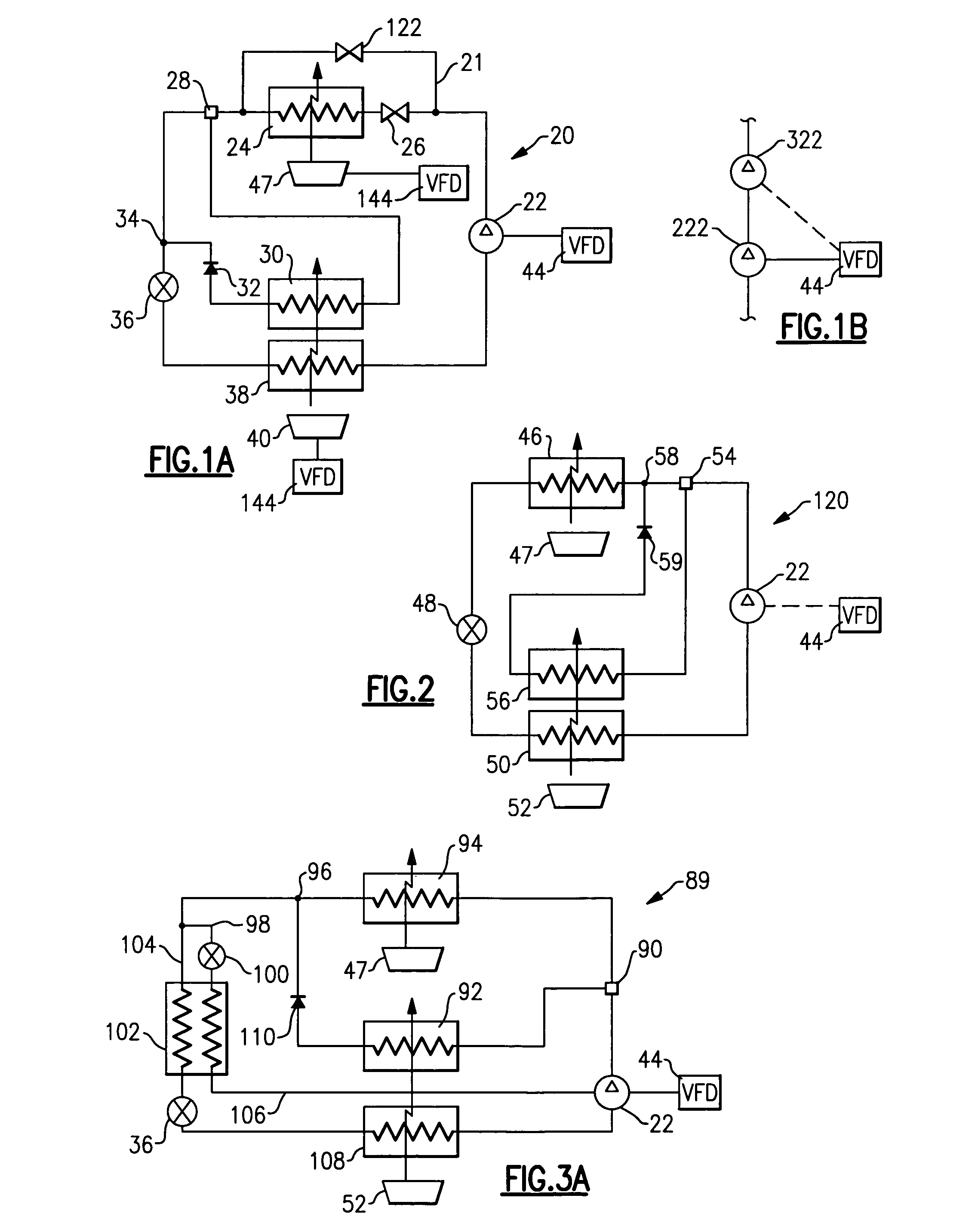
[0032]FIG. 3A shows embodiment 89, wherein the three-way valve 90 is positioned upstream of the condenser 94. When the reheat branch is in operation, refrigerant passes through the reheat coil 92, and may bypass the condenser 94, which may be maintained in an inactive mode. A check valve 110 and a return point 96 to the main cycle are shown downstream of the reheat coil 92. If an economizer expansion device 100 is open, a portion of refrigerant is rerouted through a tap line 98, economizer expansion device 100, economizer heat exchanger 102 and return line 106 to the economizer port of the compressor 22. A main refrigerant flow in a liquid line 104 also passes through the economizer heat exchanger 102 where heat transfer interaction between the two refrigerant flows (liquid high pressure refrigerant in the main loop and lower pressure refrigerant in the economizer branch) is taking place. In this embodiment, the condenser may be bypassed entirely by the refrigerant flow through the ...

embodiment 210

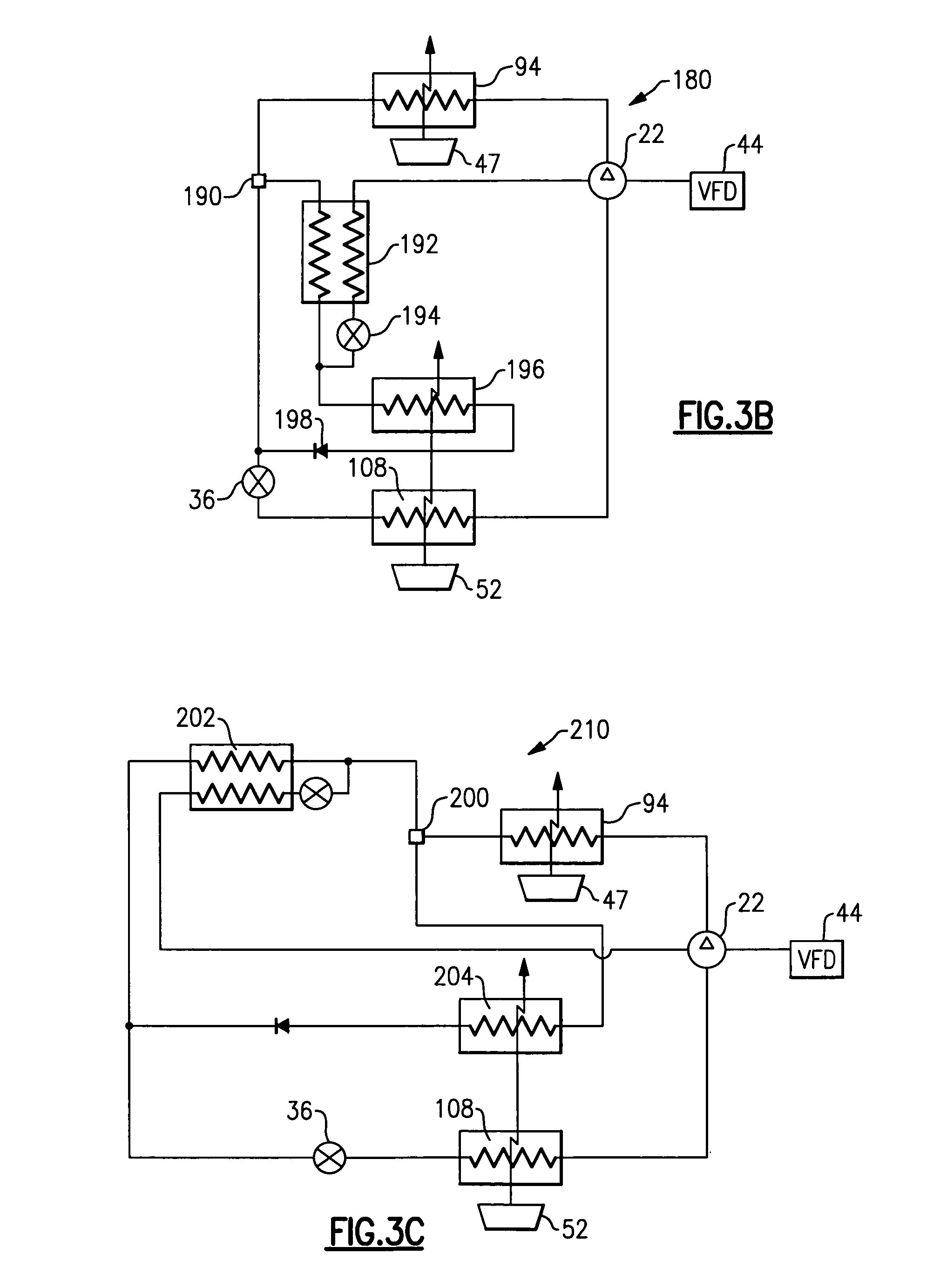
[0037]FIG. 3C shows yet another embodiment 210. In this embodiment, a three-way valve 200 selectively directs the refrigerant in a parallel flow pattern to the economizer heat exchanger 202 and to the reheat coil 204. Again, a worker in this art would recognize when a parallel flow arrangement would be more beneficial than a serial configuration.

[0038]Again, the FIGS. 1A, 1B, 2, 3A, 3B and 3C are merely an attempt to show possible reheat options. There is a large number of reheat circuit arrangements and configurations that may be utilized with the present invention. A decision on the particular reheat design concept and relative position of the reheat coil and economizer heat exchanger should be properly evaluated against specific application requirements and may have various degree of flexibility.

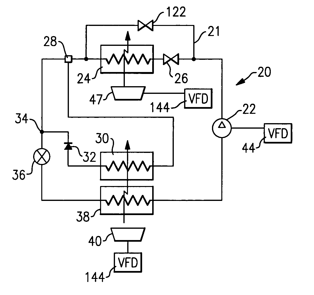
[0039]A control 44 for either refrigerant cycle 20, 120, 89, 180 and 210 is able to identify sensible and latent capacity required to provide desired temperature and humidity levels, and ...


PUM


Abstract

Refrigerant systems are provided with selectively operable components that allow variation in the capacity provided by the refrigerant system to achieve desired temperature and humidity levels. A reheat circuit is provided and an economizer circuit may also be added to the system. Typically, the reheat and economizer functions each provide a step change in the humidity control. A compressor having a variable speed drive is utilized. By providing the reheat / economizer functions along with the variable speed compressor, continuously adjustable humidity control is achieved.

Description

BACKGROUND OF THE INVENTION[0001]This invention relates to a variable speed motor for a compressor that is incorporated into a refrigerant system with a reheat function.[0002]Refrigerant systems are utilized in many applications such as to condition an environment. Air conditioners and heat pumps are used to cool and / or heat the air entering an environment. The cooling or heating load on the environment may change with ambient conditions, and as the temperature and / or humidity levels demanded by an occupant of the building vary. Obviously, the refrigerant system operation and control have to adequately reflect these changes to maintain stable temperature and humidity conditions within the environment.[0003]In some cases, while the system is operating in a cooling mode, the temperature level of the indoor air stream to provide a comfortable environment in a conditioned space may need to be higher than the temperature that would provide the ideal humidity level. On the other hand, low...

Claims


Application Information

Patent Timeline
Patent Type & Authority Patents(United States)
IPC IPC(8): F25B29/00F25B41/00F25D17/04
CPCF24F3/153F25B1/10F25B6/00F25B2400/0403F25B2400/13F25B2600/021F25B2600/111F25B2600/2507Y02B30/741Y02B30/743Y02B30/70
Inventor TARAS, MICHAEL F.LIFSON, ALEXANDER
Owner CARRIER CORP
Why Eureka
Try Eureka