
Multiple pressure regime control to minimize RH excursions during transients

a technology of transients and pressure regimes, which is applied in the direction of cell components, electrochemical generators, cell component details, etc., can solve the problems of limiting the life of the membrane, affecting the efficiency of the system, and affecting the relative humidity so as to improve the relative humidity control of the cathode outlet gas, reduce the parasitic effect of the compressor

Inactive Publication Date: 2009-04-14
GM GLOBAL TECH OPERATIONS LLC
View PDF3 Cites 8 Cited by
  • Summary
  • Abstract
  • Description
  • Claims
  • Application Information

AI Technical Summary

Benefits of technology

This approach effectively controls cathode outlet gas relative humidity, reduces membrane degradation, prevents flooding, and enhances system efficiency by minimizing compressor parasitics and RH cycling, thereby extending membrane life and maintaining consistent power output.

Problems solved by technology

MEAs are relatively expensive to manufacture and require certain conditions for effective operation.
Excessive stack temperatures may damage the membranes and other materials in the stack.
For stack durability purposes, it is desirable to minimize the number of relative humidity cycles of the membrane because cycling between RH extremes has been shown to severely limit membrane life.
This expansion and contraction of the membrane causes pin holes in the membrane, which create hydrogen and oxygen cross-over through the membrane creating hot spots that further increase the size of the hole in the membrane, thus reducing its life.
At low cell power demands, typically below 0.2 A / cm2, the water may accumulate within the flow channels because the flow rate of the reactant gas is too low to force the water out of the channels.
Those areas of the membrane that do not receive reactant gas as a result of the channel being blocked will not generate electricity, thus resulting in a non-homogenous current distribution and reducing the overall efficiency of the fuel cell.
As more and more flow channels are blocked by water, the electricity produced by the fuel cell decreases, where a cell voltage potential less than 200 mV is considered a cell failure.
However, there are certain limitations and realities that the fuel cell system must meet in order to provide efficient and effective performance.
Further, high cathode pressures at idle would cause significant compressor parasitics.

Method used


Image

  • Multiple pressure regime control to minimize RH excursions during transients
  • Multiple pressure regime control to minimize RH excursions during transients
  • Multiple pressure regime control to minimize RH excursions during transients

Examples


Embodiment Construction

[0020]The following discussion of the embodiments of the invention directed to a control system for a fuel cell stack that controls the cathode outlet gas relative humidity by changing the cathode pressure operating range during power transients is merely exemplary in nature, and is in no way intended to limit the invention or its applications or uses.

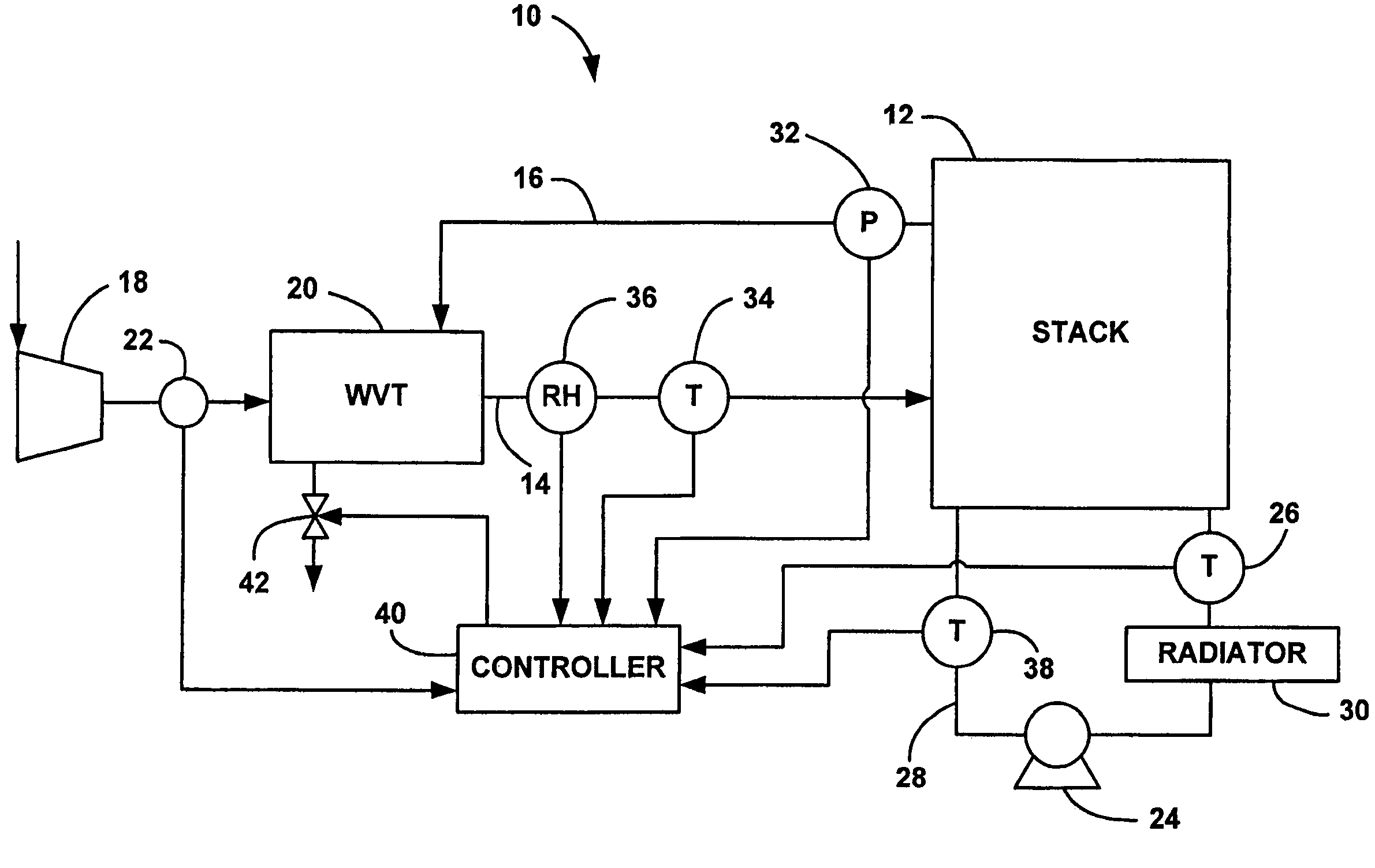
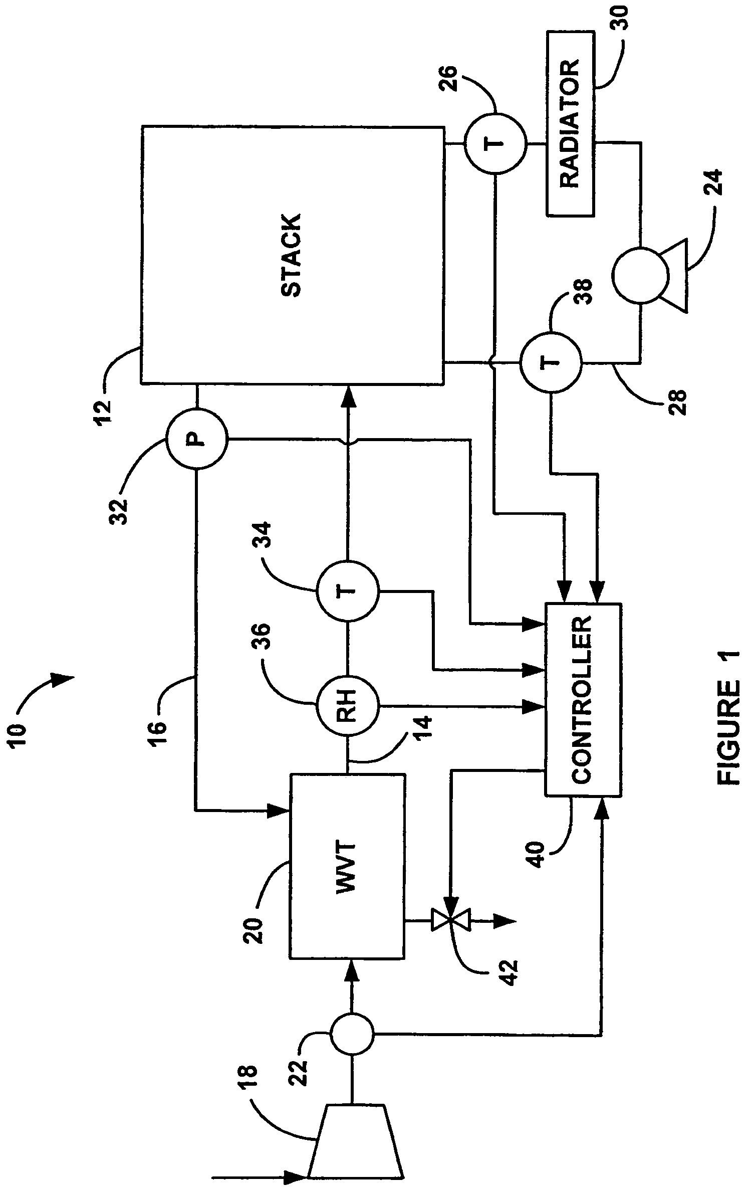
[0021]FIG. 1 is a schematic block diagram of a fuel cell system 10 including a fuel cell stack 12. The stack 12 includes a cathode input line 14 and a cathode output line 16. A compressor 18 generates a flow of air for the cathode side of the stack 12 that is sent through a WVT device 20 to be humidified. A mass flow meter 22 measures the flow rate of the air from the compressor. The humidified air is input into the stack 12 on the line 14, and humidified cathode exhaust gas is provided on the output line 16. The cathode exhaust gas on the line 16 is sent through the WVT device 20 to provide the water vapor for humidifying the cathode ...


PUM

PropertyMeasurementUnit
timeaaaaaaaaaa
cell voltage potentialaaaaaaaaaa
pressureaaaaaaaaaa

Abstract

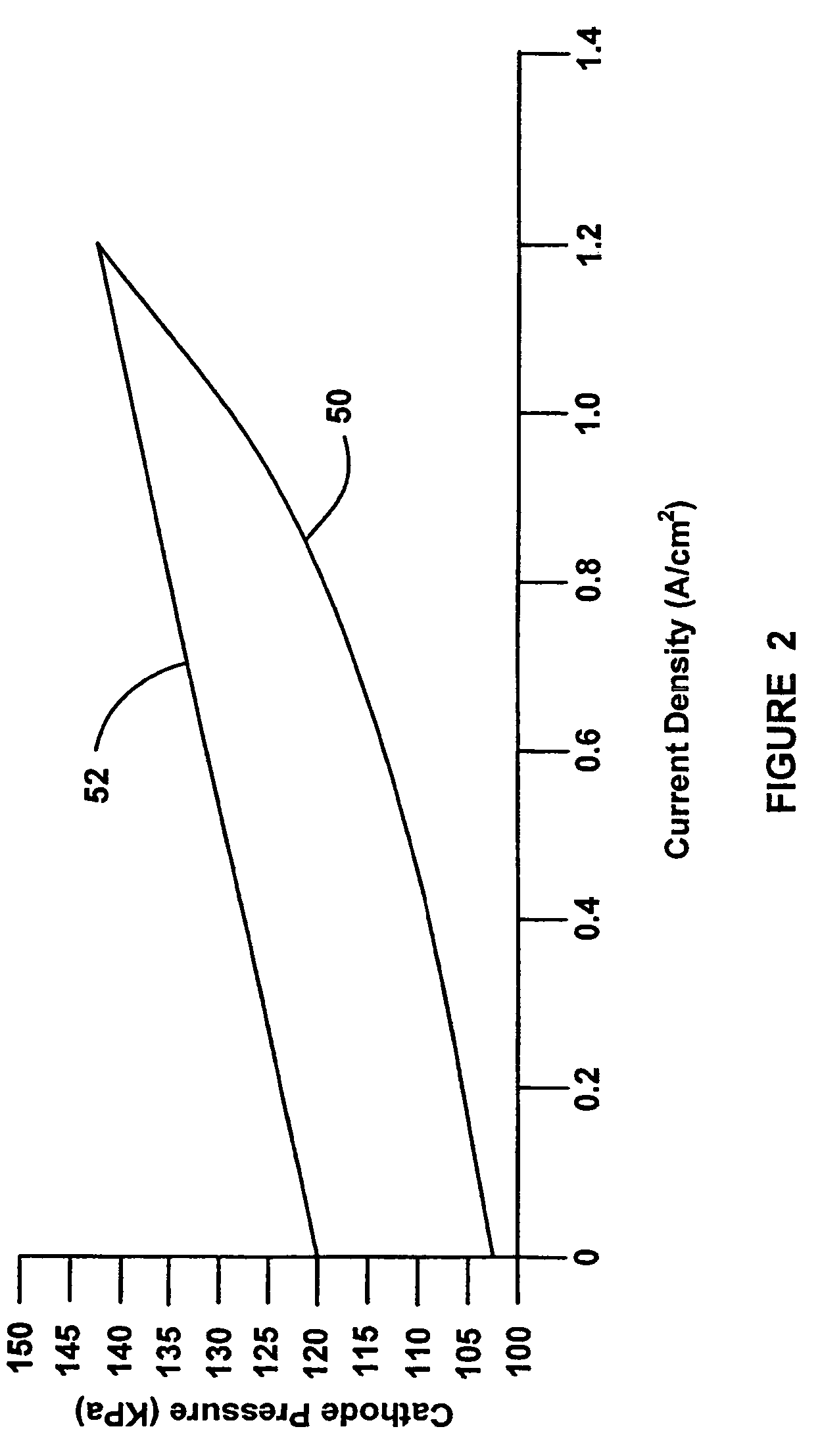
A control system for a fuel cell stack that controls the relative humidity of the cathode outlet gas during stack power transients to provide better cathode outlet gas relative humidity control by reducing the dynamic pressure range and thus the dynamic cathode outlet gas relative humidity range. In one embodiment, the control system uses a first narrower cathode pressure range based on stack current density during stack power transients to provide better cathode outlet gas relative humidity control, and uses a second wider cathode pressure range based on stack current density during low current density and steady-state current density to improve system efficiency by decreasing compressor parasitics.

Description

BACKGROUND OF THE INVENTION[0001]1. Field of the Invention[0002]This invention relates generally to a system and method for controlling the relative humidity of the cathode exhaust gas from a fuel cell stack and, more particularly, to a system and method for controlling the relative humidity of the cathode exhaust gas from a fuel cell stack that includes changing the operating range of the cathode pressure based on stack current density during stack power transients.[0003]2. Discussion of the Related Art[0004]Hydrogen is a very attractive fuel because it is clean and can be used to efficiently produce electricity in a fuel cell. A hydrogen fuel cell is an electro-chemical device that includes an anode and a cathode with an electrolyte therebetween. The anode receives hydrogen gas and the cathode receives oxygen or air. The hydrogen gas is dissociated in the anode to generate free hydrogen protons and electrons. The hydrogen protons pass through the electrolyte to the cathode. The hy...

Claims


Application Information

Patent Timeline
Patent Type & Authority Patents(United States)
IPC IPC(8): H01M8/04
CPCH01M8/04126H01M8/04291H01M8/04589H01M8/04753H01M8/04761H01M8/04843H01M8/04231H01M8/04253H01M8/04335H01M8/0435H01M8/04708H01M8/04716H01M2008/1095Y02E60/50
Inventor ARTHUR, DAVID A.SINHA, MANISH
Owner GM GLOBAL TECH OPERATIONS LLC
Learn More