Face equipment comprising hose levels placed between the face conveyor and the shield support frames

Inactive Publication Date: 2016-11-01
RAG AG
View PDF10 Cites 0 Cited by
  • Summary
  • Abstract
  • Description
  • Claims
  • Application Information

AI Technical Summary

Benefits of technology

The patent text describes a hose configuration for a shield support frame in mining operations. The hose is designed with a pressure sensor to measure the height difference between the face conveyor and the roof canopy. This allows for improved accuracy in measuring the face height perpendicular to the stratification. The hose can be designed as a closed or open hose level, with a pressure accumulator to dampen hydraulic pressure fluctuations and protect the sensors. A two-sensor system can also be used to measure the height difference between the face conveyor and the roof canopy, allowing for barometric correction and minimizing errors.

Problems solved by technology

The known procedure is associated with the disadvantage of complex computing operations, which further require that the base data valid for the respective design of the used shield support frame be accurately determined, and that a useable algorithm be generated for calculating the height perpendicular to the stratification of the shield support frame.

Method used


Image

  • Face equipment comprising hose levels placed between the face conveyor and the shield support frames
  • Face equipment comprising hose levels placed between the face conveyor and the shield support frames
  • Face equipment comprising hose levels placed between the face conveyor and the shield support frames

Examples


Embodiment Construction

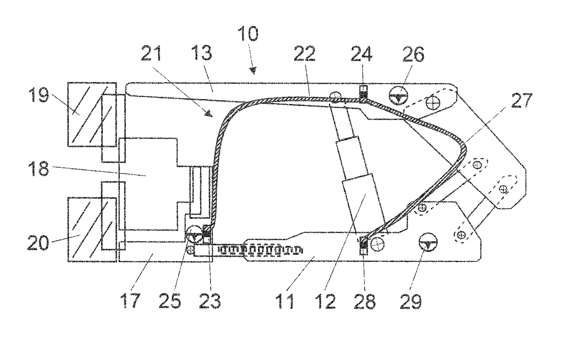
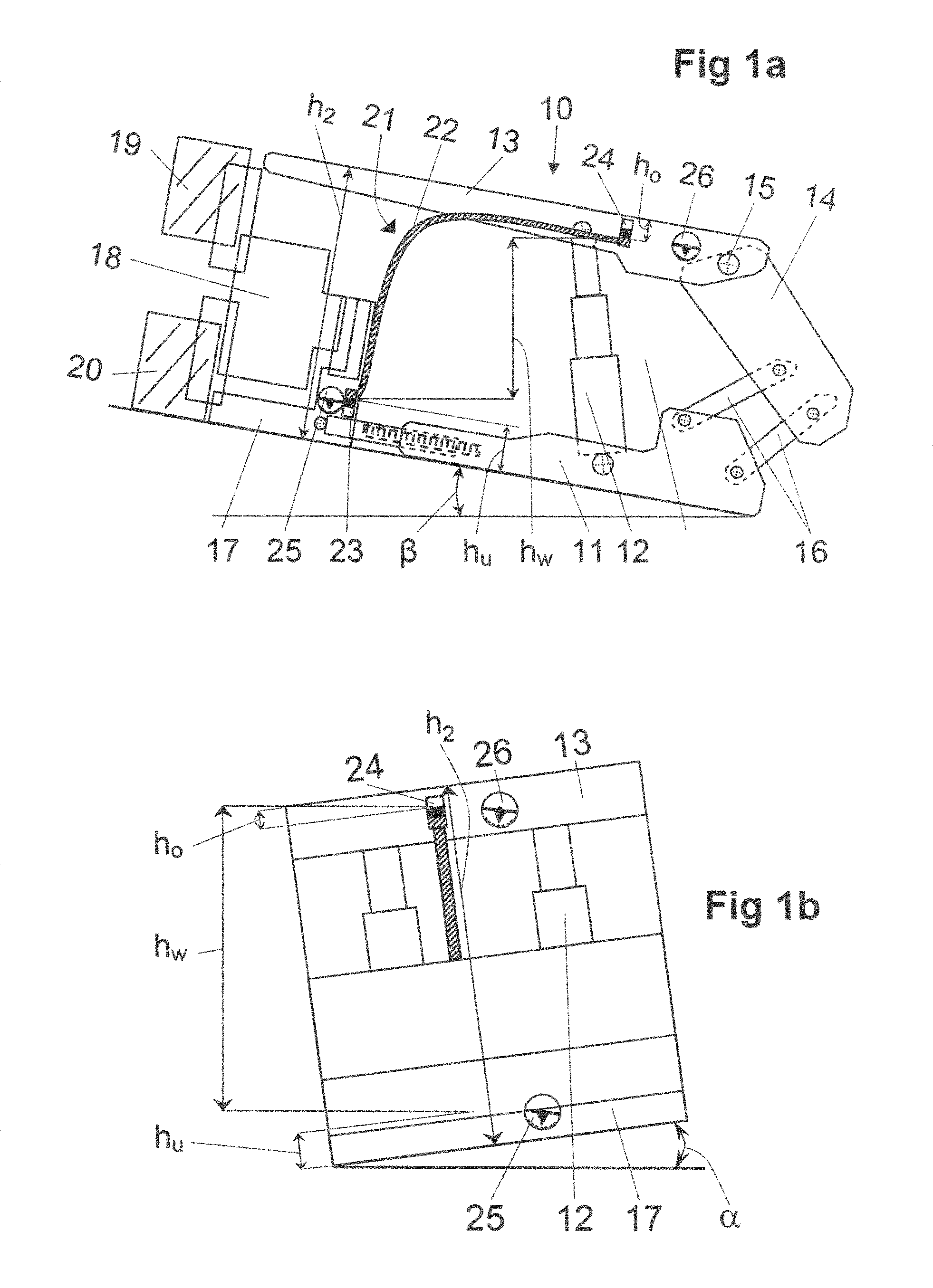
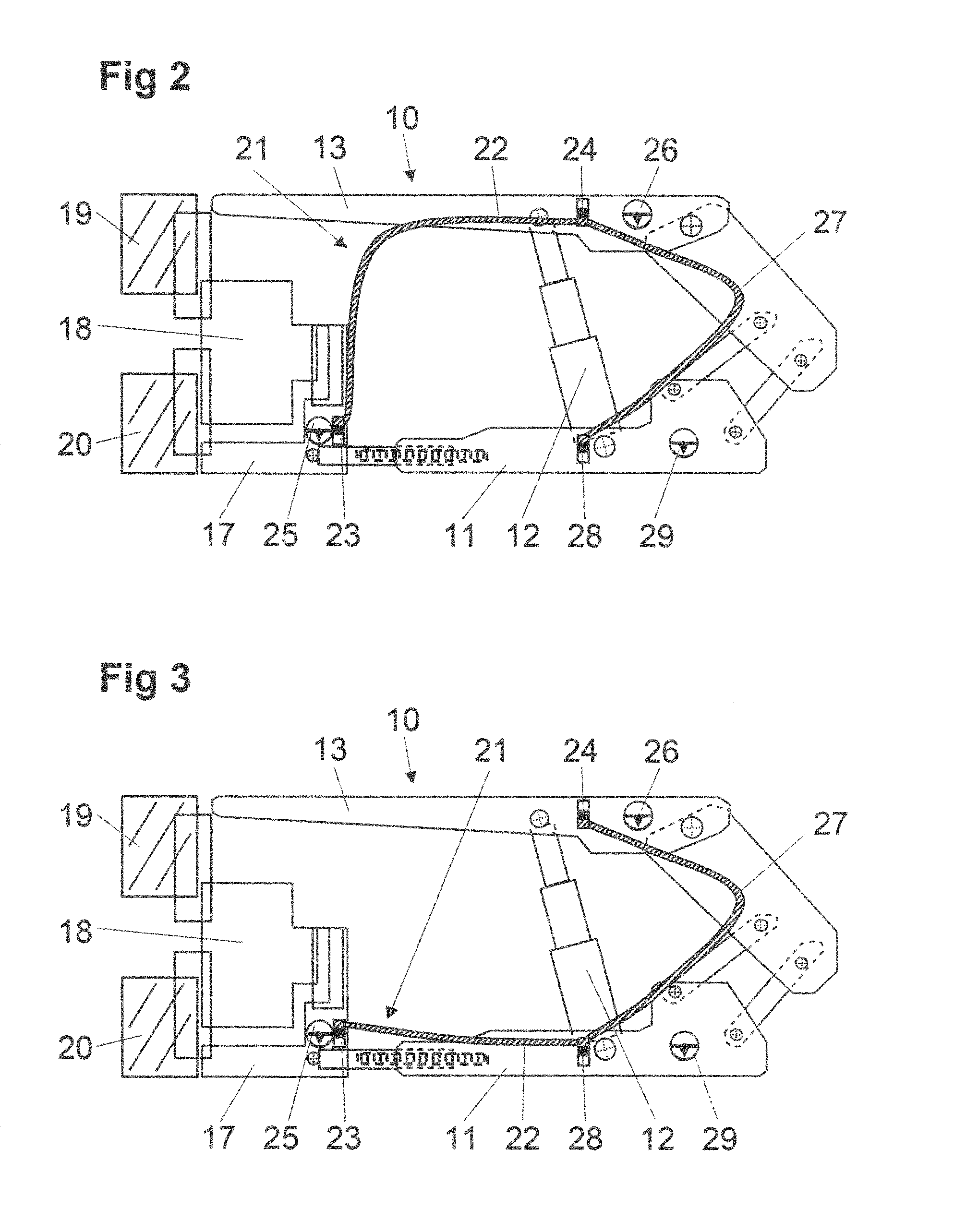
[0034]The face equipment schematically depicted on FIG. 1a initially encompasses a shield support frame 10 with a floor skid 11, which has attached to it two parallel arranged props 12, of which only one prop can be seen on FIG. 1a, and whose upper end bears a roof canopy 13. A gob shield 14 is secured to the rear (right) end of the roof canopy 13 by means of a hinge 15, wherein the gob shield 14 is supported by two support connection rods 16 resting on the floor skid 11 in the side view. The front (left) end of the roof canopy 13 protrudes over a face conveyor 17, upon which can travel an extraction machine 18 designed as a disc shearer with a hanging wall disc 19 and footwall disc 20.

[0035]Situated between the face conveyor 17 and the roof canopy 13 of the shield support frame 10 is a flexible hose level 21 with a hose 22 running freely between the face conveyor 17 and roof canopy 13, whose lower end is arranged on the face conveyor 17, and whose upper end is arranged on the roof ...


PUM


Abstract

A face equipment for mechanical extraction in longwall mining, in particular in the underground hard coal mining industry, includes a face conveyor (17) arranged along the mining wall, an extraction device (18) that can be moved along the face conveyor (17), and shield support frames (10) supported on the face conveyor (17) at an angle thereto. In order to determine the height of the face opening, a flexible hose level (21) with a liquid-filled hose (22) placed between the face conveyor (17) and at least one main component of the shield support frame (10) is installed in the area of the face conveyor (17). A pressure sensor (23, 24, 28) is arranged on at least one end of the hose (22). An inclination measuring device (25, 26) is arranged on the face conveyor (17) and on the main component of the shield support frame (10).

Description

[0001]The instant application should be granted the priority date Apr. 2, 2012, the filing date of the international patent application PCT / EP2012 / 055990.BACKGROUND OF THE INVENTION[0002]The invention relates to a face equipment for mechanical extraction in longwall mining, in particular in the underground hard coal mining industry, with a face conveyor arranged along the mining wall, an extraction means that can be moved along the face conveyor, and shield support frames supported on the face conveyor at an angle thereto.[0003]WO 2009 / 103303 describes a face equipment with the aforementioned features along with a method for controlling such a face equipment. To this end, the above publication explains in detail that automating such a controller for the face equipment generally depends on knowing where the face equipment is positioned in the room, but especially on knowing the respective height of the face opening that exists in the region of the front end of the roof canopy of the ...

Claims


Application Information

Patent Timeline
IPC IPC(8): E21D23/16G01C5/04E21D23/12E21C27/00
CPCE21D23/16E21C27/00E21D23/12G01C5/04E21D23/0004E21D23/0409
Inventor JUNKER, MARTINMOZAR, ARMIN
Owner RAG AG
Why Eureka
Try Eureka