Method of manufacturing a pipe coupling component
a manufacturing method and technology of a pipe coupling are applied in the direction of hose connections, lighting and heating apparatus, and semiconductor/solid-state device details. the effect of preventing the formation of a relatively large clearan
- Summary
- Abstract
- Description
- Claims
- Application Information
AI Technical Summary
Benefits of technology
Problems solved by technology
Method used
Image
Examples
embodiment 1
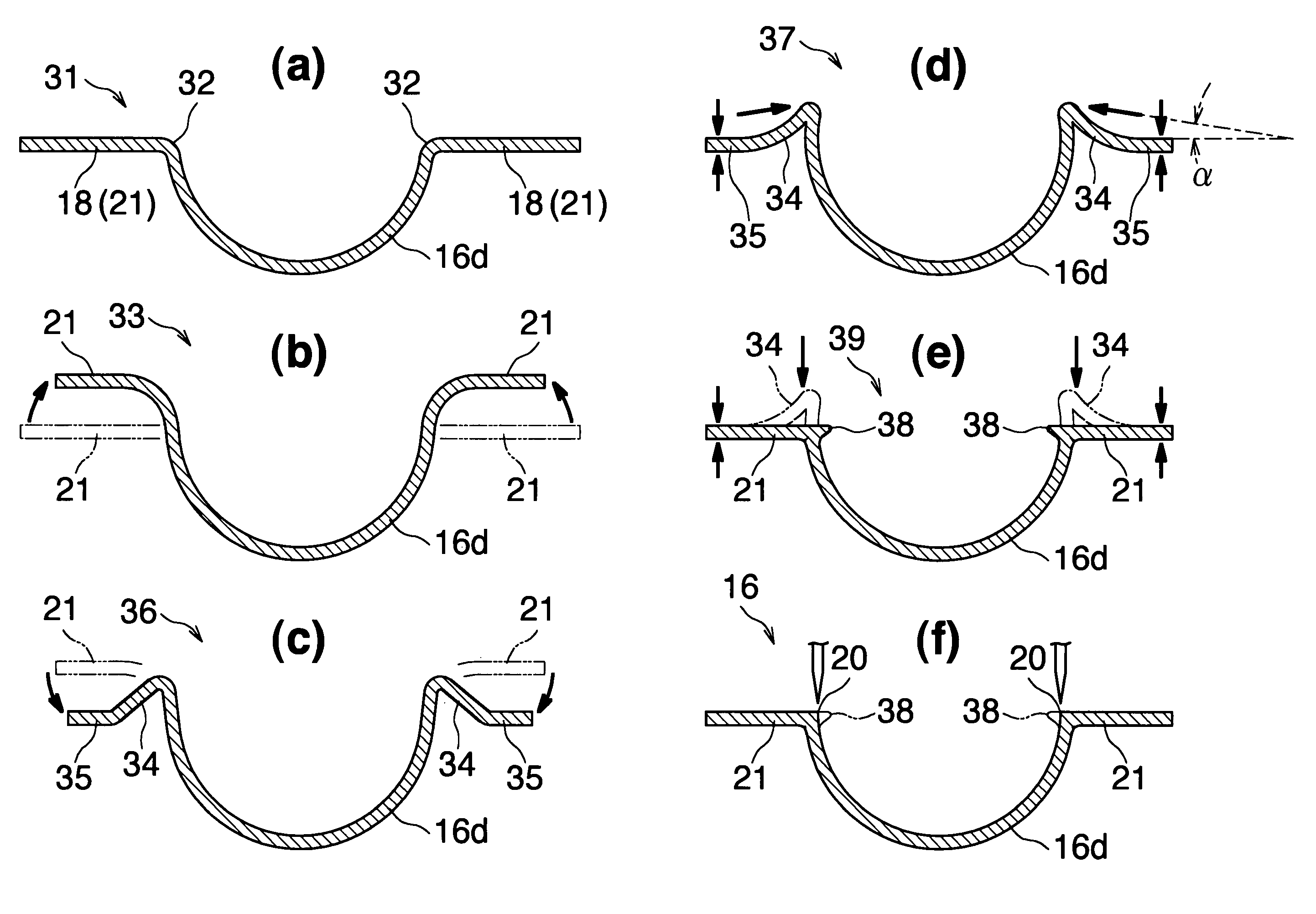
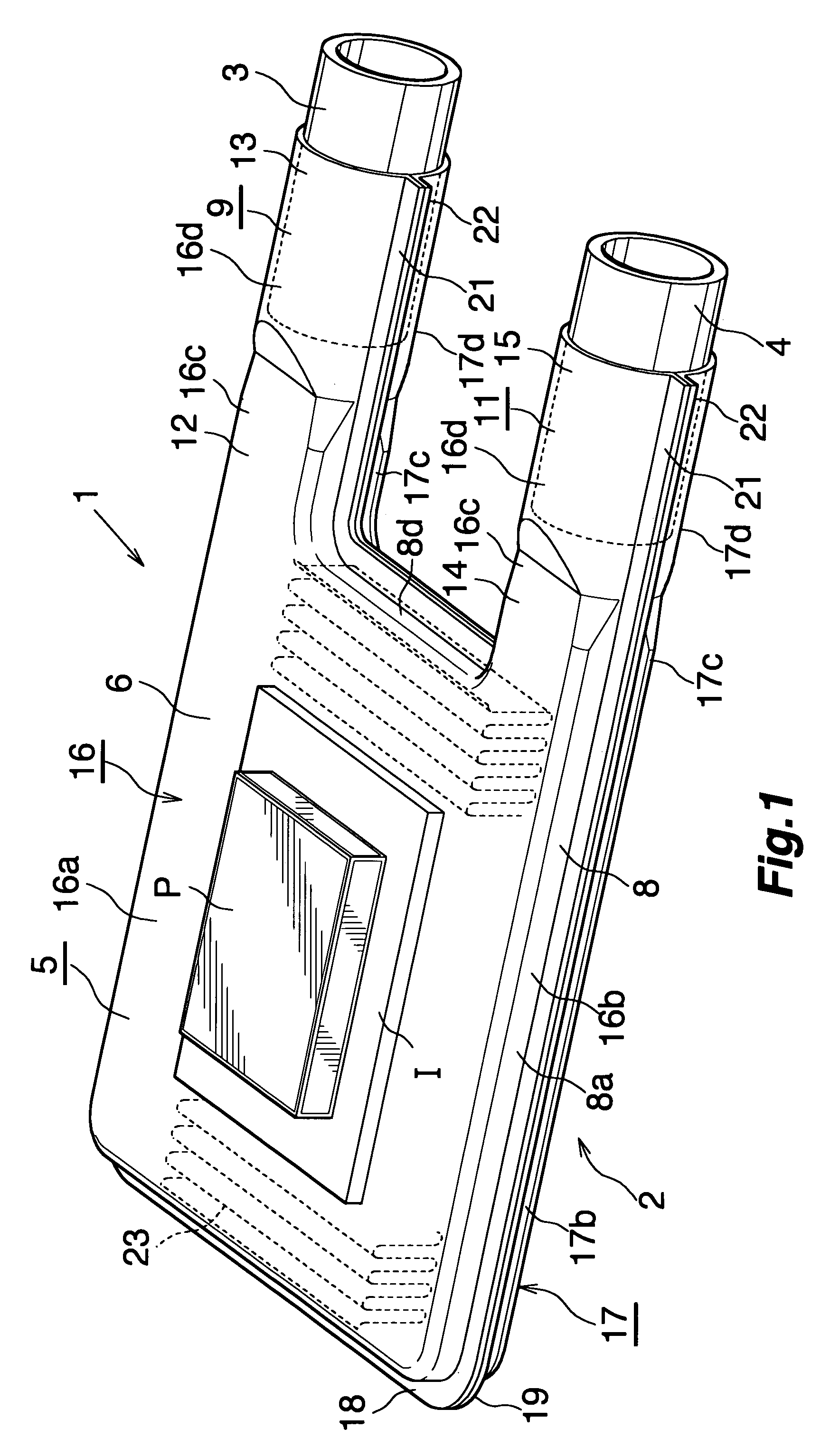
[0044]FIGS. 1 to 6 show the present embodiment in which the method of manufacturing a casing structural member according to the present invention is applied to manufacture of casing structural members of a liquid-cooled-type cooling apparatus.
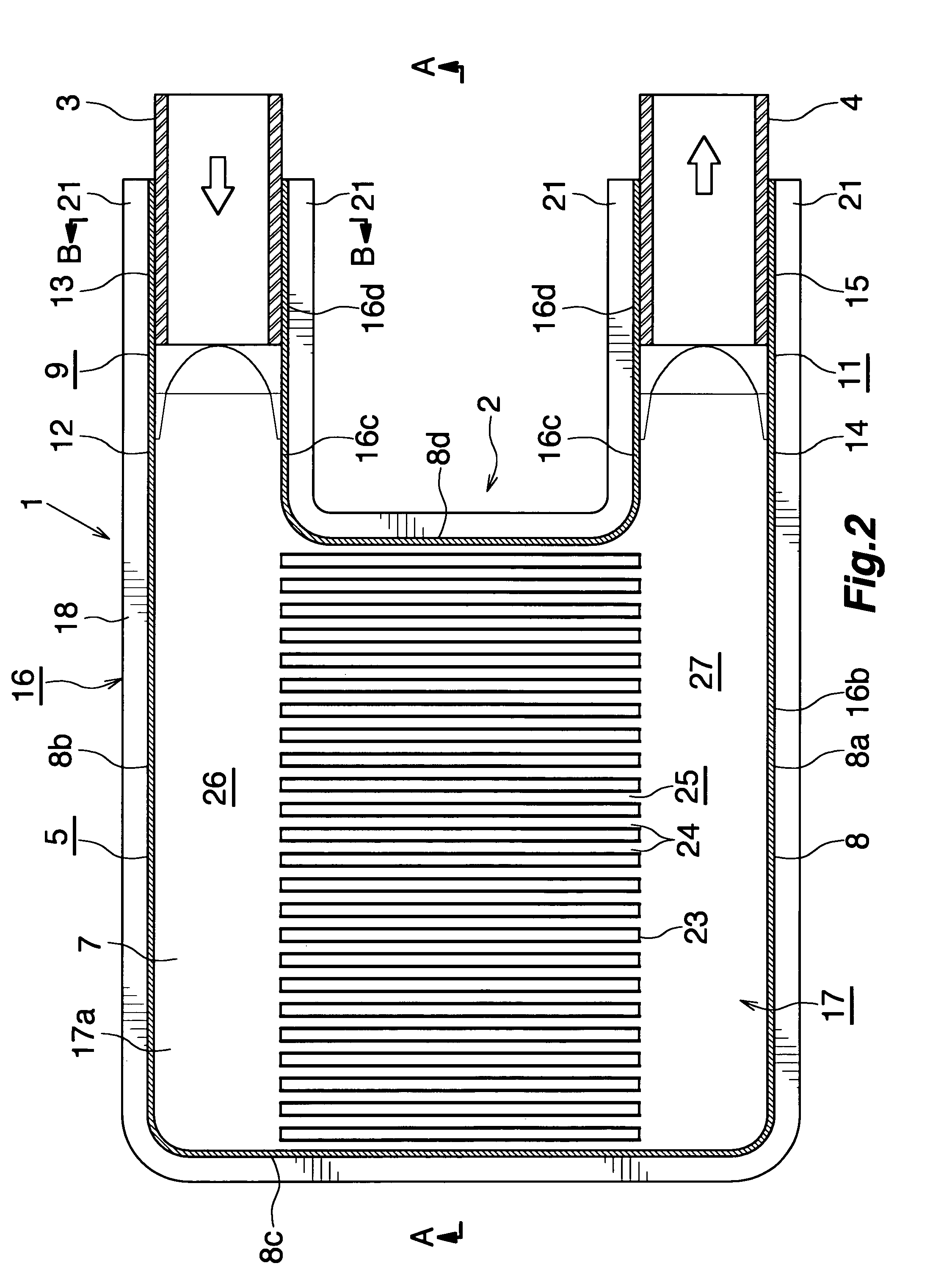
[0045]FIGS. 1 to 4 show a liquid-cooled-type cooling apparatus which includes a casing composed of structural members manufactured by the method of the present invention. FIGS. 5 and 6 show a method of manufacturing the structural members of the casing.
[0046]Notably, in the description of the liquid-cooled-type cooling apparatus based on FIGS. 1 to 4, the lower side of FIG. 2 will be referred to as the front, and the upper side of FIG. 2 will be referred to as the rear; and the upper, lower, left-hand, and right-hand sides of FIG. 3 will be referred to as “upper,”“lower,”“left,” and “right,” respectively.
[0047]In FIGS. 1 to 3, a liquid-cooled-type cooling apparatus (1) comprises a hollow casing (2); an inflow pipe (3) formed of a round pipe and...
embodiment 2
[0064]FIGS. 7 to 13 show this embodiment in which the structure for coupling a pipe to a hollow component according to the present invention is applied to coupling of inflow and outflow pipes to pipe coupling portions of a casing of a liquid-cooled-type cooling apparatus.
[0065]FIGS. 7 to 11 show a liquid-cooled-type cooling apparatus having a casing to which pipes are connected by use of the pipe coupling structure of the present invention. FIGS. 12 to 13 show a method of coupling the pipes to the casing.
[0066]Notably, in the description, the lower side of FIG. 8 will be referred to as the front, and the upper side of FIG. 8 will be referred to as the rear; and the upper, lower, left-hand, and right-hand sides of FIG. 9 will be referred to as “upper,”“lower,”“left,” and “right,” respectively.
[0067]In FIGS. 7 to 9, each of the upper and lower structural members (16) (17) of the liquid-cooled-type cooling apparatus (1) is formed through press work performed on an aluminum brazing shee...
embodiment 3
[0074]FIGS. 14 to 16 show the present embodiment in which the structure for coupling a pipe to a hollow component according to the present invention is applied to connection of inflow and outflow pipes to pipe coupling portions of a casing of a liquid-cooled-type cooling apparatus.
[0075]In the case of the structure according to the present embodiment for coupling the inflow pipe (3) and the outflow pipe (4) to the pipe coupling portions (13) (15) of the casing (2), a first outward extending flange (50) is provided at the distal end portion of the pipe coupling portion (13) (15) so that the flange surrounds the coupling portion forming portions (16d) (17d) and the horizontal flat portions (21) (22) of the upper and lower structural members (16) (17). The outer circumferential edge of the annular portion (50a) of the first outward extending flange (50) is located radially outward of the round portions (40) formed at the boundaries between the inner circumferential surface of the coupl...
PUM
| Property | Measurement | Unit |
|---|---|---|
| inclination angle | aaaaa | aaaaa |
| width | aaaaa | aaaaa |
| depth | aaaaa | aaaaa |
Abstract
Description
Claims
Application Information
 - R&D
- Intellectual Property
- Life Sciences
- Materials
- Tech Scout
- Unparalleled Data Quality
- Higher Quality Content
- 60% Fewer Hallucinations
Browse by: Latest US Patents, China's latest patents, Technical Efficacy Thesaurus, Application Domain, Technology Topic, Popular Technical Reports.
© 2025 PatSnap. All rights reserved.Legal|Privacy policy|Modern Slavery Act Transparency Statement|Sitemap|About US| Contact US: help@patsnap.com


