Wave energy absorber

a technology of wave energy and absorber, which is applied in the direction of electric generator control, machines/engines, mechanical equipment, etc., can solve the problems of high cost, complex and expensive amounts of sea energy, and the limited availability of wave energy generation near shore, so as to maximize the energy absorbed in operation, increase the volume of expandable elements, and provide hydrostatic stability

Inactive Publication Date: 2013-04-16
SINGLE BUOY MOORINGS INC
View PDF21 Cites 11 Cited by
  • Summary
  • Abstract
  • Description
  • Claims
  • Application Information

AI Technical Summary

Benefits of technology

[0025]One advantage of the present invention is that the relief valve opens if a preset maximum tension force is reached in one of the mooring lines while a pumping device (that can be actuated via electricity produced by the wave power unit) is used to increase the volume of the expandable elements and by that the effective surface of the buoyant structure when the tension in one or more mooring lines is below a preset minimum. This principle creates a natural control loop of the wave load on the body that maximizes the energy absorbed in operation while protecting the system against excessive tension.
[0026]Preferably, the power control unit and the power transfer system are placed in the dry environment of the main buoyancy structure.
[0027]Another advantage of the present invention is that the buoyancy structure is provided with one part that protrudes through the sea surface, and that can be provided with a door above the water surface, so to give access to the interior of the main buoyant structure and to provide hydrostatic stability.
[0028]According to the present invention, the buoyancy structure is provided with at least two sets of inclined taut mooring lines provided with an extension member and a clump weight, each set consisting of two taut mooring lines which axes are intersecting near the buoyant structure. The extension members may have a variable stiffness so that they ensure a stiff connection between the linear generator and the seabed in operation and a soft connection under harsh survival conditions.
[0029]A further advantage of the present invention is that the expandable element can be fitted with a spring loaded appendage that is activated by the pressurization of the expandable element so that the flushing of the fluid out of the expandable element, for instance prior to storm conditions, is totally passive.
[0030]The present wave energy absorber is based on a taut mooring using cables which cannot transfer compressive loads. Therefore, the linear generator should ideally work only on the extension of the lines. Therefore, the present invention is well suited to the use of stretchable dielectric material (such as EAP) as linear generator because they typically store elastic energy during the first half of the cycle (stretching) and convert it to electrical energy during the other half (back to original length). Stretchable dielectric material does not generate electrical power under compression.

Problems solved by technology

Furthermore, near shore area available for wave energy generating is often restricted due to harbor and leisure activities.
The apparatus may also include mooring systems that maintain the complete apparatus in a position that is consistent with design requirements and regulatory demands and not significantly inhibit its efficient operation.
However, such an apparatus requires at least two bodies with a complex guiding system.Other devices that have been developed:
A common problem with existing devices designed to recover significant amounts of energy from the sea is their complexity and cost.
Most devices proposed are very demanding in terms of engineering design, deployment and maintenance.
Another main problem remaining is how to design an apparatus that at the same time is the efficient in operation and is able to withstand harsh offshore conditions.

Method used


Image

  • Wave energy absorber
  • Wave energy absorber
  • Wave energy absorber

Examples


Embodiment Construction

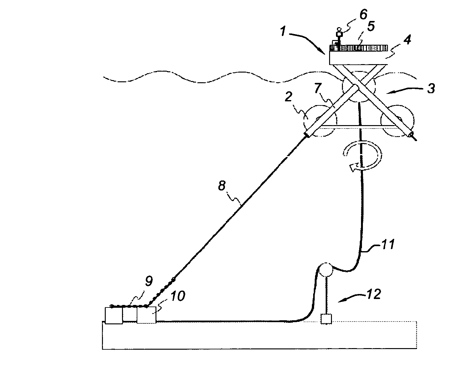
[0045]In the present invention, the wave energy absorber is used to absorb the energy of waves using the fundamental principles of the Bristol cylinder.

[0046]In a Bristol cylinder, wave forces on a submerged cylindrical body are substantially changed if the cylindrical element is being rotated around the axis of the cylinder. In fact, throughout the motion of the cylinders, energy will be absorbed through a power conversion mechanism, which converts the slow reciprocating motion into usable energy. According to the present invention the power conversion system is placed within the buoyant structure in a dry environment.

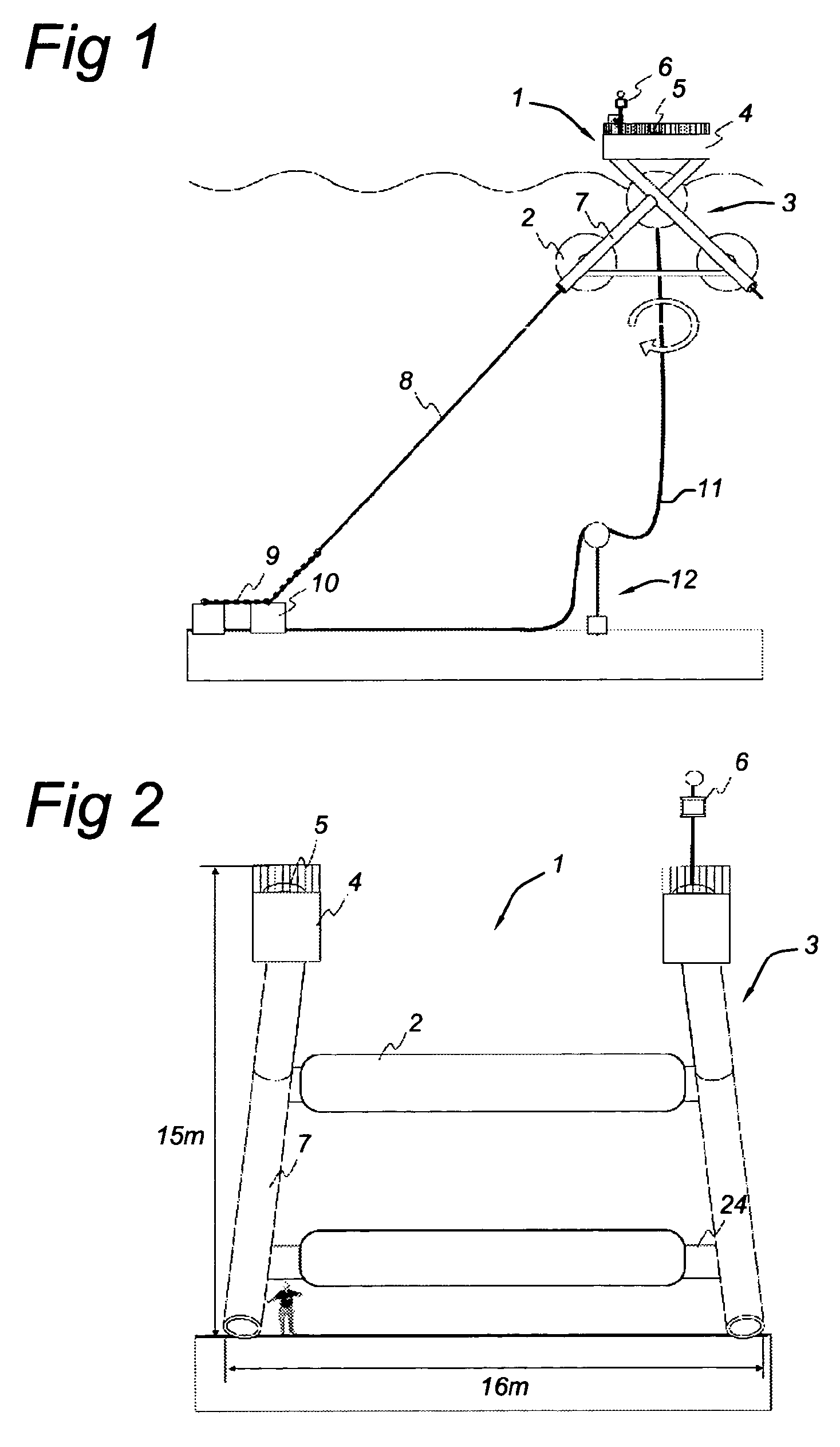
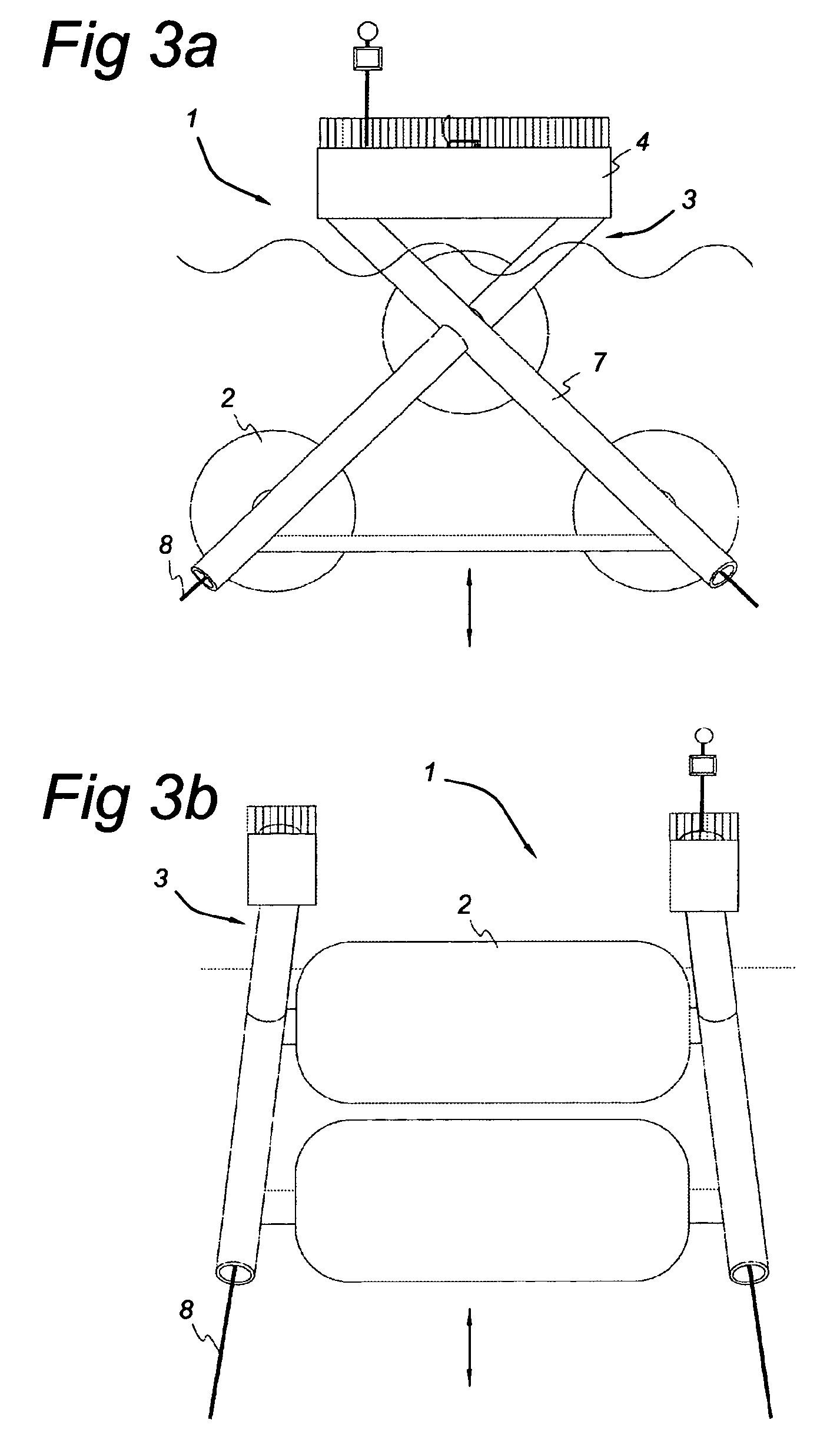
[0047]FIG. 1 shows a side view of an embodiment of an overall installation including the wave energy absorber shown in FIG. 1. The wave energy absorber 1 is composed, in this particular embodiment, of three expandable elements 2 that are part of a buoyant structure 3 taut moored to the seabed via taut mooring lines 8. The deck structure 4 is supported above sea level....


PUM


Abstract

A wave-power unit for extracting in an efficient way energy from waves on a water surface in different offshore conditions, including a main buoyant structure moored to the seabed with taut mooring lines and placed at a submerged, wave active depth, a linear generator placed within the buoyant structure and activated via a taut mooring line. The unit also includes a power take off cable connected to the linear generator and leading via the seabed to shore, and is characterized in that the buoyant structure is provided with fixed buoyancy and with elements to vary the surface of the buoyant structure that is exposed to the dynamic pressure of the wave, to optimize the surface for an efficient power take-off for more than one wave frequency and to control the tension in the taut mooring lines.

Description

BACKGROUND OF THE INVENTION[0001]This invention relates to the capture of energy from waves on the surface of a body of water and, particularly, to a power generating system using a taut moored wave energy absorber.[0002]Various systems are known for capturing energy from waves passing along the surface of a body of water, particularly an ocean where quite large and powerful waves are consistently present.[0003]Wave energy is lost by friction with the sea bottom as the sea becomes shallow (water depths of half a wavelength or less). This is most pronounced where wavelengths tend to be long. Furthermore, near shore area available for wave energy generating is often restricted due to harbor and leisure activities. Therefore, the preferred location for the present invention would be in water depths greater than 50 m in locations several miles from shore.[0004]Wave Energy Converters (WECs) may be classified in different ways according to their operating principle and the ways in which t...

Claims


Application Information

Patent Timeline
Patent Type & Authority Patents(United States)
IPC IPC(8): F03B13/10H02P9/04F03B13/12
CPCF03B13/1865Y02E10/38Y02E10/30
Inventor ARDOISE, GUILLAUME ANDRE JEAN-LOUISJEAN, PHILIPPE FRANCOIS MICHEL GEORGES
Owner SINGLE BUOY MOORINGS INC
Why Eureka
Try Eureka