

Pulsed free induction decay nonlinear magneto-optical rotation apparatus
a nonlinear, magneto-optical rotation, free induction decay technology, applied in the field of magnetometers, can solve the problems of difficult confinement to atomic vapor, larmor frequency, long wavelength of rf field,
- Summary
- Abstract
- Description
- Claims
- Application Information
AI Technical Summary
Benefits of technology
Problems solved by technology
Method used
Image

Examples
Embodiment Construction
[0028]The present invention is of a free induction decay NMOR (FID NMOR) and concomitant methods. Advantages of FID NMOR include but are not limited to:
[0029]No broadening from the pump beam during the probing sequence, hence, high pumping power creates a stronger signal, without increasing the relaxation rate.
[0030]One beam can be used as both pump and probe, without adverse modulation effects on the probe beam.
[0031]Pumping can use AM modulation, FM modulation and / or tone burst modulation.
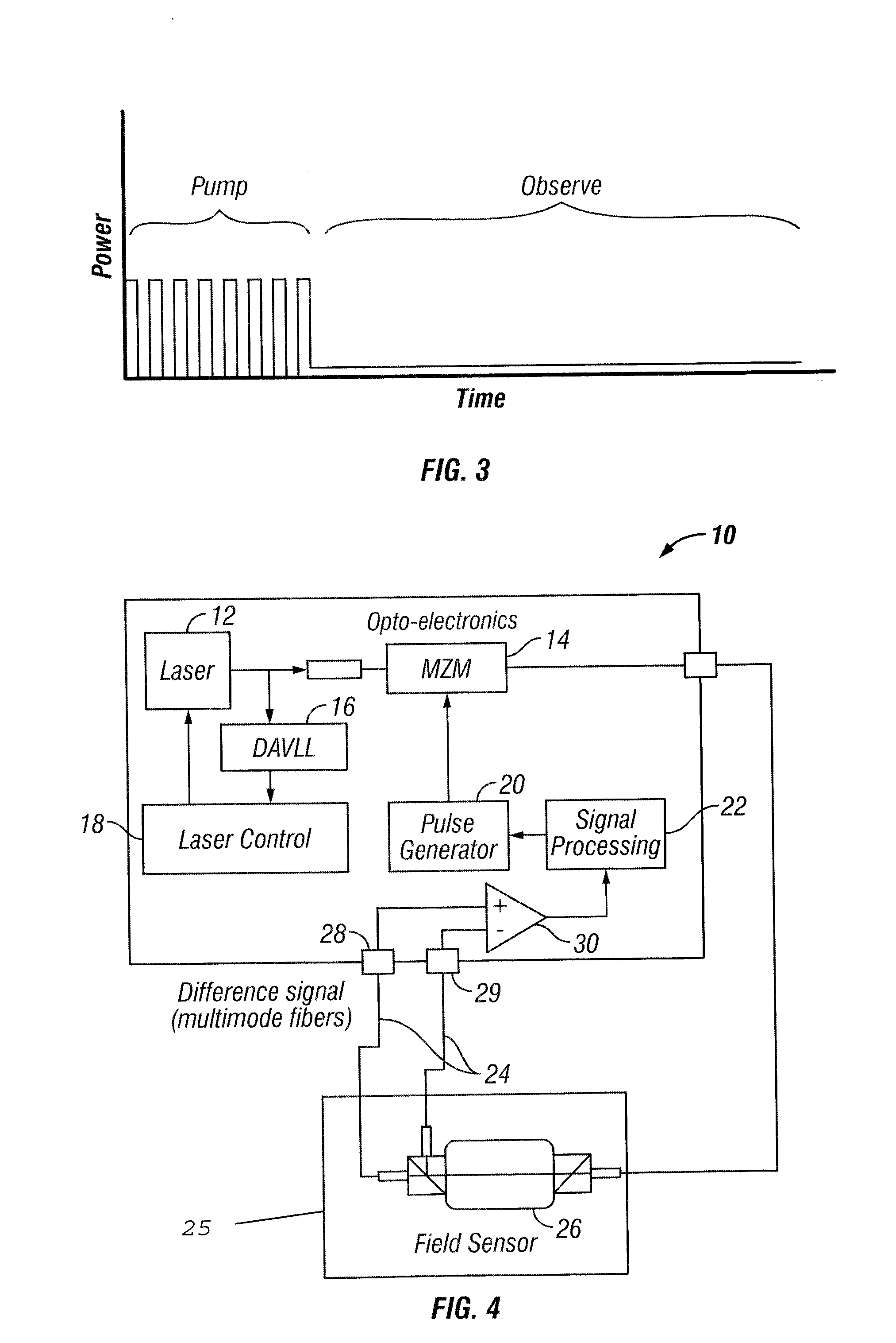
[0032]Pumping can be accomplished in a single pulse (if sufficient power is available) or in a series of pulses, each of lower power.
[0033]Detection can be accomplished by monitoring fluorescent light emitted from the atoms while the pump beam is off.
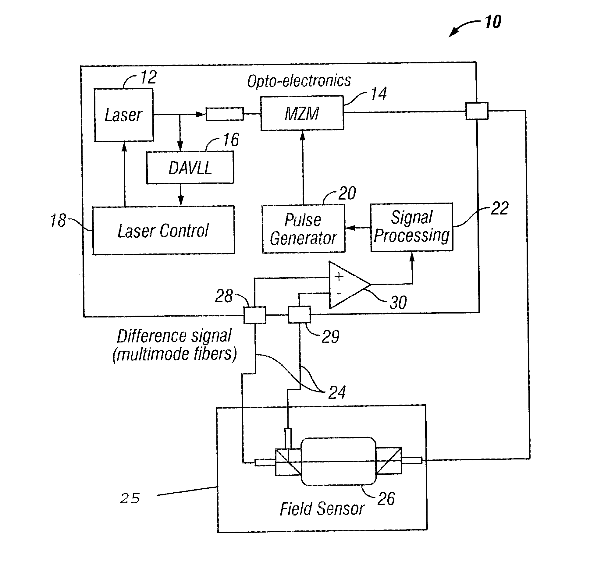
[0034]Pump and probe lasers can propagate in the same direction without the need to spatially separate them. This is useful for remote excitation and probing of NMOR signals.[0035]In one embodiment of the present invention and as illustrated in FIG. ...
PUM
 Abstract
Description
Claims
Application Information