AC current sensor for measuring electric AC current in a conductor and an indicator system comprising such a sensor

a technology of electric ac current and sensor, which is applied in the direction of short-circuit testing, air-break switch details, transmission, etc., can solve the problems of reducing maintenance and planning costs of electric power distribution companies, not being able to detect, convey, and too costly, so as to reduce maintenance time and planning costs. , the effect of reducing the time needed

Inactive Publication Date: 2013-04-16
THIIM2 APS
View PDF32 Cites 37 Cited by
  • Summary
  • Abstract
  • Description
  • Claims
  • Application Information

AI Technical Summary

Benefits of technology

[0024]The non-electrical wave signal is preferably a light signal from a LED, and the provision of a pulsed signal during normal state currents providing substantially real time current measurements rather than a single error signal during other current states, such as a short circuit, enables a wide range of applications for said sensor.
[0082]An indicator system according to a further embodiment of the invention, said detection unit is provided integrally with said current sensor. Alternatively, depending on viewpoint, one or more current sensors may be provided integrally with said detection unit. This is in particular an advantage when monitoring LV lines, where high voltage solation is not required between the two.

Problems solved by technology

In particular when measuring high voltage AC power lines, the problem is to determine the occurrence of such short circuit, e.g. by measuring the current or more correctly the short circuit current, without a potential connection to the electric AC power line, which would be too costly due to the requirement of having a high degree of insulation between conductor and ground, e.g. a remotely positioned indicator unit.
This considerably decreases maintenance and planning costs for the electric power distribution companies.
However, said known detector may not be sufficiently fast to both sense, detect and convey all instances of short circuits during the available detection time period before the line current has reached zero.
Further, said detector may not be sufficiently precise to distinguish between rush-in current peaks and real short circuits resulting in blown fuses.
Thus, the prevalent technical prejudice has been that self-sufficient current sensors in the above mentioned two types of known indicator systems for HV power lines have been too slow to indicate nearby short circuits, in particular if attempted applied to LV and MV power lines.
As stated in the document a disadvantage of these Faraday effect sensors is that there are sources for disturbances of the detection of the polarization change of the light signal, comprising optical noise in the detection circuit, electrical noise in light source, interference from magnetic fields from nearby inductors and systems, sensor mounting and setup, conductor shape and diameter, sensor production tolerances, temperature effects on light source and detector, light source and detector degradation over the products lifetime.
Thus, calibration both prior to commencing measurements and during monitoring the lines is necessary, which increases the costs of the sensor and indicator units alike.
Given the fact that a large number of devices is required for enabling a network monitoring system, this increases the total cost of the disclosed system.
However, said device is not suitable for monitoring HV or even MV conductors, because the device needs to be sufficiently electrically insulated between conductor and ground.
This is due to the fact that the device utilises a low voltage optical isolator, and the device may only at a high cost be adapted to higher voltage applications.
Accordingly, an application to HV and MV AC conductors would require the application of an expensive electrical isolation between device and conductor, or indicator and ground.
Further, the sensor disclosed is too slow to provide time-realistic current values as it provides an average current value measured over a relatively long sampling time period, i.e. more than one cycle period, as may be seen from the circuit diagram provided.

Method used


Image

  • AC current sensor for measuring electric AC current in a conductor and an indicator system comprising such a sensor
  • AC current sensor for measuring electric AC current in a conductor and an indicator system comprising such a sensor
  • AC current sensor for measuring electric AC current in a conductor and an indicator system comprising such a sensor

Examples


first embodiment

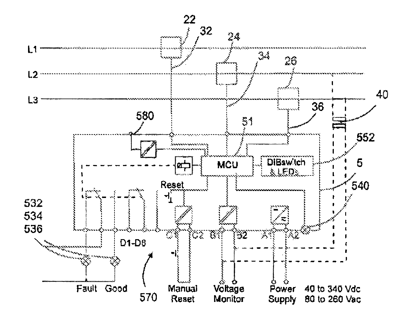
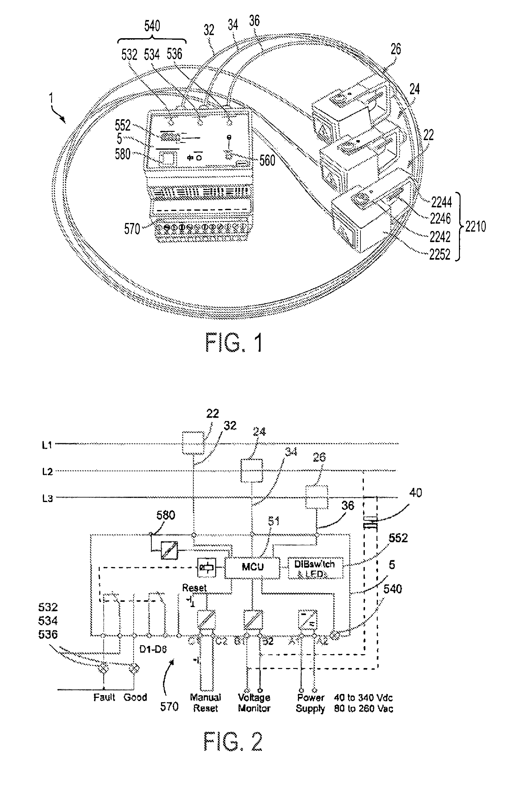
[0103]Said voltage measurement means may be provided in two ways: In a first embodiment said voltage measurement means is a separate voltage measurement monitor 40, as shown in FIG. 2, which may be the provided by the main transformer used at the site, providing a measurement to be relayed to the MCU for a determination as to whether the voltage is lost, i.e. below said voltage threshold Vmin, e.g. from 10 to 50% of nominal voltage or less, after said predetermined time period t1.

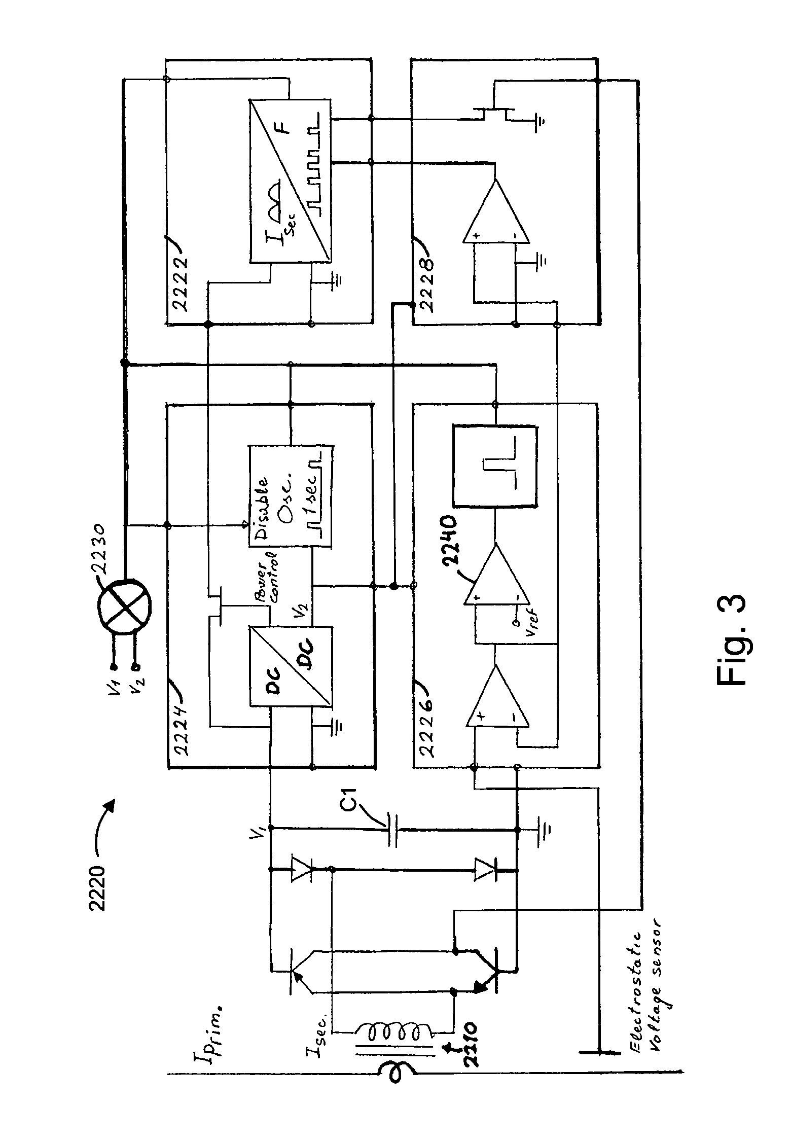
[0104]In a second embodiment, the voltage measurement means and voltage threshold means are provided integrally 2240 within the current sensor 22 in a voltage lost indication circuitry 2226, as indicated in FIG. 3, for providing an electrostatic voltage measurement of said electric conductor, which may be implemented using various available components, being adapted to provide said non-electrical wave signal as a voltage lost indication signal VLS, the presence of which is indicating that the voltage over s...

second embodiment

[0116]As shown in FIG. 3, the sensor circuitry 2220 further comprises power flow direction indication circuitry 2228. Two different embodiments are contemplated, a first 2228A for providing information concerning voltage measurements for a subsequent power flow direction determination in the detection unit 5, e.g. providing two distinct pulse signals having each their pulse frequency PfPA and PfPP, one corresponding to the phase angle and one the polarity of said measured voltage, said pulse signals being emitted from said means for emitting a non-electrical wave signal; and a second embodiment, wherein the flow direction determination is performed within the sensor circuitry, providing a singular pulse signal having binary values based on a continuous determination of the current flow direction. Other ways of indicating power flow direction is known to the skilled person, relayed to the detection unit 5. Correspondingly, the detection unit 5 is able to differentiate and translate t...


PUM


Abstract

The invention concerns a current sensor (22; 24; 26) for substantially in real time measuring electric current in a conductor. It is suitable for application in an indicator system (1) such as a short circuit indicator system for measuring instantaneous i.e. live current value, power, reactive power, phase angle, polarity, short circuits, in single or averaged values. It comprises current responsive means comprising a current transformer (2210), adapted for mounting adjacent to said electric conductor; and sensor circuitry (2220) comprising means for emitting a non-electrical wave signal as an output; said sensor circuitry (2220) comprises current level converter circuitry (2222) comprising a current-to-frequency converter adapted to provide said non-electrical wave signal as a current level indication pulse signal (CS1) having a pulse frequency (Pfcs) which is proportional to said real time electric conductor current, when the latter is within a predetermined current interval (I1-I2). Thus, a low cost sensor is provided. The invention further relates to an indicator system (1) for an electric conductor comprising at least one of the above mentioned current sensors (22; 24; 26).

Description

TECHNICAL FIELD OF THE INVENTION[0001]The present invention relates to a current sensor for performing a substantially real time measurement of electric AC current magnitude in a conductor, comprising current responsive means comprising a current transformer adapted for mounting adjacent to said current conductor; and sensor circuitry comprising means for emitting a non-electrical wave signal as an output. The present invention further relates to an indicator system comprising such a sensor, suitable for processing said non-electrical wave signal for different monitoring purposes, such as indicating short circuits.BACKGROUND OF THE INVENTION[0002]Current sensors are available, which are being used for a wide range of applications, such as being part of indicator systems indicating different electrical states in a conductor based thereupon, such as momentary and average current values, power values, the presence of short circuits, faults on the line, circuit breaker cut outs and the ...

Claims


Application Information

Patent Timeline
Patent Type & Authority Patents(United States)
IPC IPC(8): G01R31/02H04B3/46
CPCG01R19/252G01R31/025G01R19/16547G01R19/2513G01R31/52
Inventor THIIM, SOREN
Owner THIIM2 APS
Why Eureka
Try Eureka