Carbon dioxide detector having borosilicate substrate

a carbon dioxide and substrate technology, applied in the direction of material analysis, optical radiation measurement, biomass after-treatment, etc., can solve the problems of carbon dioxide level, perfusion failure, and tube may have been incorrectly placed, and achieve the effect of acceptable carbon dioxide sensitivity

Active Publication Date: 2013-04-30
TYCO HEALTHCARE GRP LP
View PDF195 Cites 2 Cited by
  • Summary
  • Abstract
  • Description
  • Claims
  • Application Information

AI Technical Summary

Benefits of technology

[0018]Another embodiment relates to a carbon dioxide detector having a carbon dioxide responsive indicator solution disposed on a ...

Problems solved by technology

If only low carbon dioxide levels consistent with placement in the esophagus are present, then the tube may have been incorrectly placed and may need to be removed and r...

Method used


Image

  • Carbon dioxide detector having borosilicate substrate
  • Carbon dioxide detector having borosilicate substrate
  • Carbon dioxide detector having borosilicate substrate

Examples


Embodiment Construction

[0035]The present disclosure relates to a calorimetric carbon dioxide detector having a borosilicate substrate.

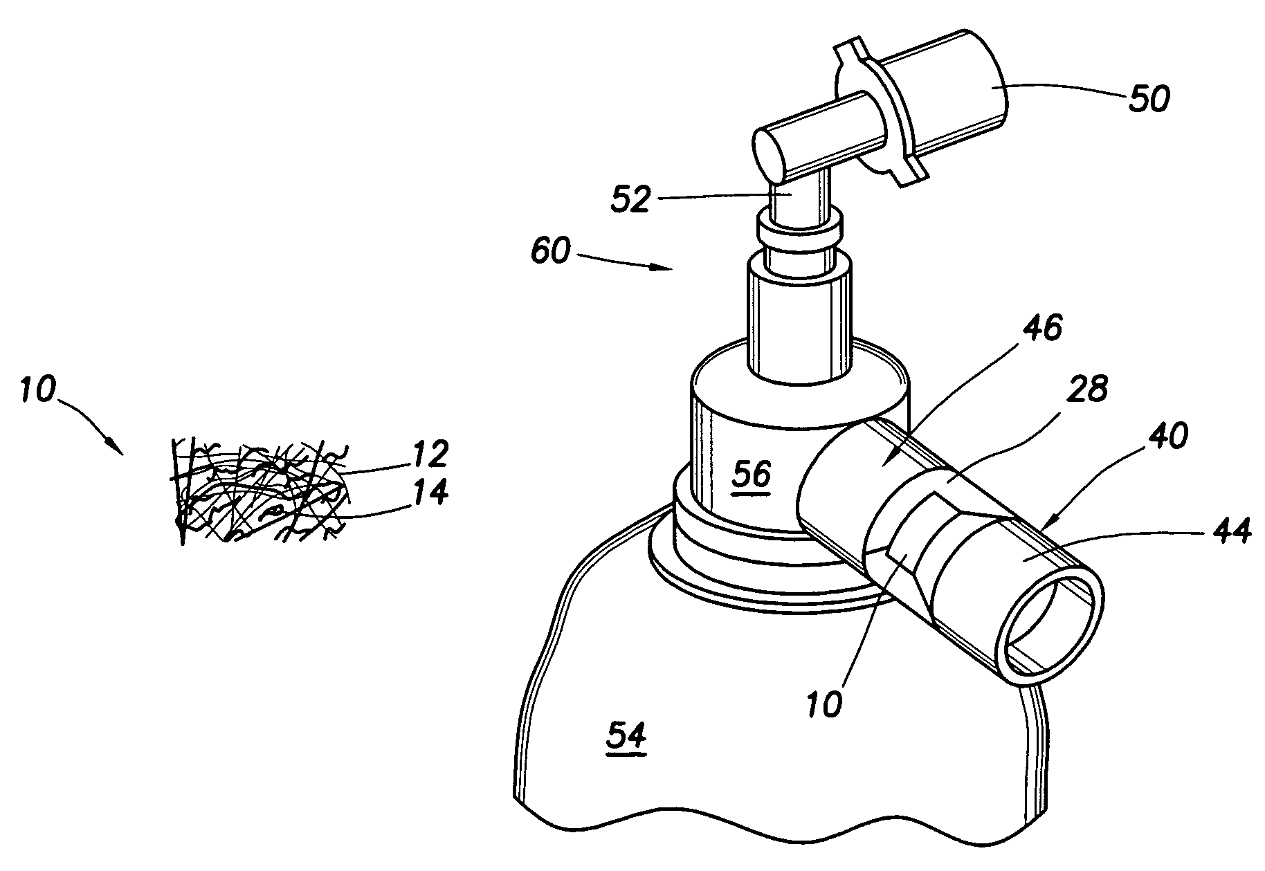
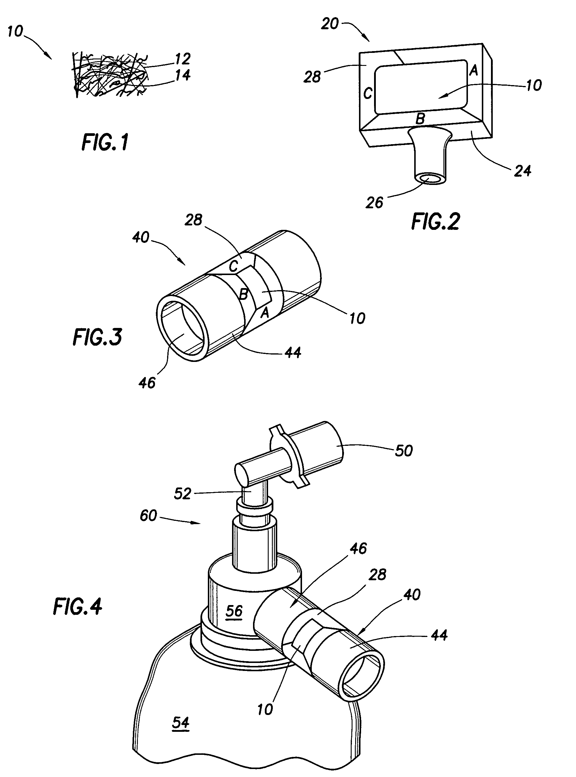
[0036]In a specific embodiment, shown in FIG. 1, detector 10 may include substrate 12 and indicator solution 14. Detector 10 may be sized appropriately for use in a detector system, such as those shown in FIGS. 2 and 3.

[0037]Substrate 12 may include any borosilicate-containing material. Specifically, it may include borosilicate fibers. These fibers may be produced using any conventional methods, such as melt blowing and spinning. The substrate may include a mesh of borosilicate fibers. More specifically, it may include a thin, highly porous mesh to facilitate rapid infiltration of carbon dioxide gas into the substrate.

[0038]Borosilicate may be sufficiently hydrophilic to allow indicator solution 14 to spread evenly over substrate 12 and be well absorbed when it is first applied. Indicator solution 14 may then be dried, but still retain sufficient water to allow reaction wit...


PUM

PropertyMeasurementUnit
Fractionaaaaaaaaaa
Timeaaaaaaaaaa
Timeaaaaaaaaaa

Abstract

The present disclosure relates to a carbon dioxide detector having a borosilicate substrate. It may also have a carbon dioxide responsive indicator solution disposed on the borosilicate substrate. The carbon dioxide detector may be part of a carbon dioxide detector system also including an air intake operably connected to the housing to allow air to reach the carbon dioxide detector. The carbon dioxide detector may include a borosilicate substrate and a carbon dioxide responsive indicator solution disposed on the borosilicate substrate. This detector may be part of a further system, such as a resuscitation system. The detector may be made by wetting a borosilicate substrate with a carbon dioxide responsive indicator solution and drying the indicator solution to immobilize it and form a dried carbon dioxide detector. It may be used to detect the concentration of carbon dioxide in an air sample by exposing the detector to the sample.

Description

TECHNICAL FIELD[0001]The present disclosure relates to a carbon dioxide detector having a borosilicate substrate.BACKGROUND[0002]This section is intended to introduce the reader to various aspects of art that may be related to various aspects of the present invention, which are described and / or claimed below. This discussion is believed to be helpful in providing the reader with background information to facilitate a better understanding of the various aspects of the present invention. Accordingly, it should be understood that these statements are to be read in this light, and not as admissions of prior art.[0003]Respiratory gasses may be readily distinguished from non-respiratory gasses by carbon dioxide content. Exhaled respiratory gas in a human typically contains between 3% and 5% carbon dioxide. In contrast, ambient air has only approximately 0.03% carbon dioxide. Normal esophageal gas has similarly low levels of carbon dioxide.[0004]The detection of respiratory gasses via carb...

Claims


Application Information

Patent Timeline
IPC IPC(8): G01N21/75
CPCB01J20/10B01J20/2803B01J20/28033G01N31/223A61B5/0836A61M2016/103A61M2230/432B01J2220/49
Inventor OSTROWSKI, RAFAELDEBRECZENY, MARTIN
Owner TYCO HEALTHCARE GRP LP
Why Eureka
Try Eureka