Electrode for recording and stimulation

Active Publication Date: 2013-05-07
PMT
View PDF12 Cites 9 Cited by
  • Summary
  • Abstract
  • Description
  • Claims
  • Application Information

AI Technical Summary

Benefits of technology

[0008]An advantage of the present invention is to provide enhanced surface electrodes wherein the electrode grid or strip has a textured surface to increase malleability for conformance to the surface features of the brain. Another advantage is to provide an electrode grid or strip having a textured surface to reduce adhesion to smooth and wet surfaces of the brain, dermal, and/or skull.
[0009]Another advantage is to provide a method for forming an electrode with a textured surface by means of a coating applied as a subsequent operation to the dielectric silicone or flexible polymer material. Another advantage is to provide a method for forming an electrode with a textured surface by means of a “lost wax technique” wherein salt or another water soluble material is applied to the uncured dielectric material of the grid or strip. The material then being cured and the water soluble material removed via a de-ionized (DI) water application. Another advantage is to provide an el

Problems solved by technology

This interconnection cable is necessary because the electrical connectors in

Method used


Image

  • Electrode for recording and stimulation
  • Electrode for recording and stimulation
  • Electrode for recording and stimulation

Examples


embodiment 10

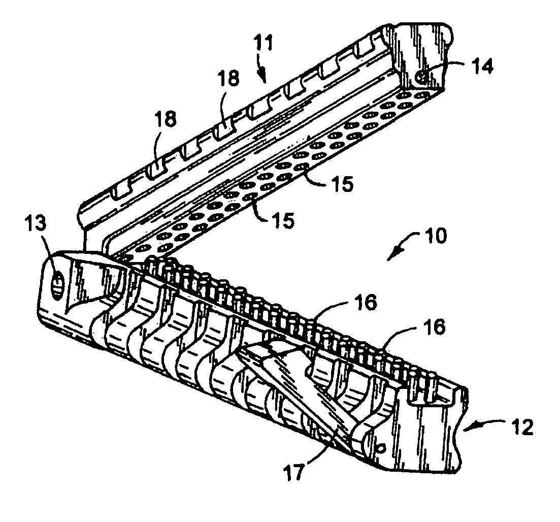
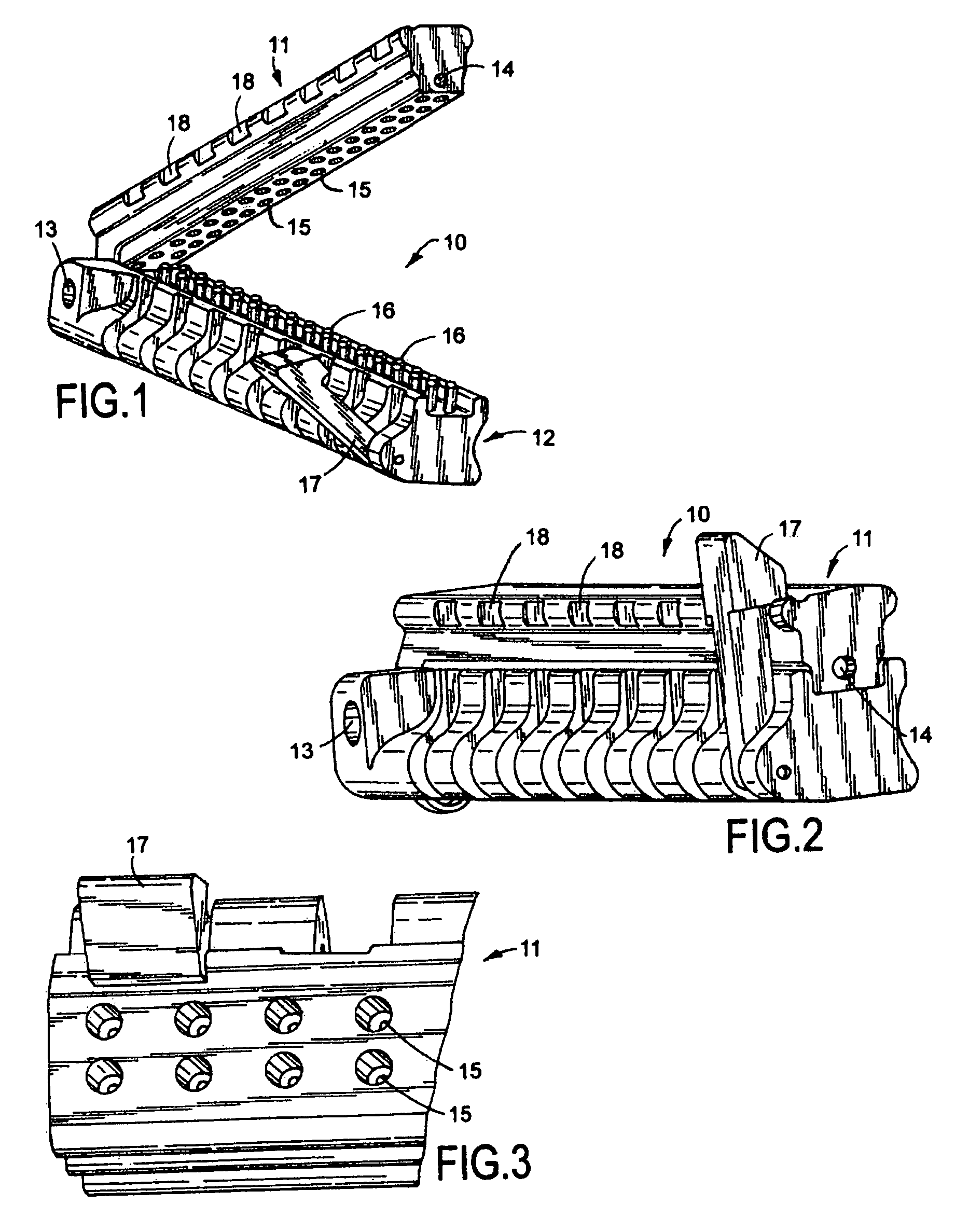
[0039]Referring to FIGS. 1-3, the connector assembly embodiment 10 shows a hinged two-piece connector having a top member 11, and a bottom member 12. The top member rotates with respect to bottom member 12 by means of hinge 13 which is disposed perpendicular to the connector's contact pins 16 (2 rows) and positioned adjacent to the distal tip or end of the inline tail of the electrode when placed in the assembly. The contact pins 16 may be constructed of stainless steel, platinum, a platinum alloy, or of a shape memory alloy (SMA) as further discussed below.

[0040]The hinge 13 may use a dowel (not shown) that is perpendicular to the length of the inline connector structure and perpendicular to the connector pins 16 extending upwardly in the bottom body 12 of the connector assembly. The dowel may be a screw that threads into one side of the connector, a dowel with a recess for a pin, or an e-clip. The hinge 13 may also be a press fit pin that bottoms out and is sealed in or enclosed w...

embodiment 20

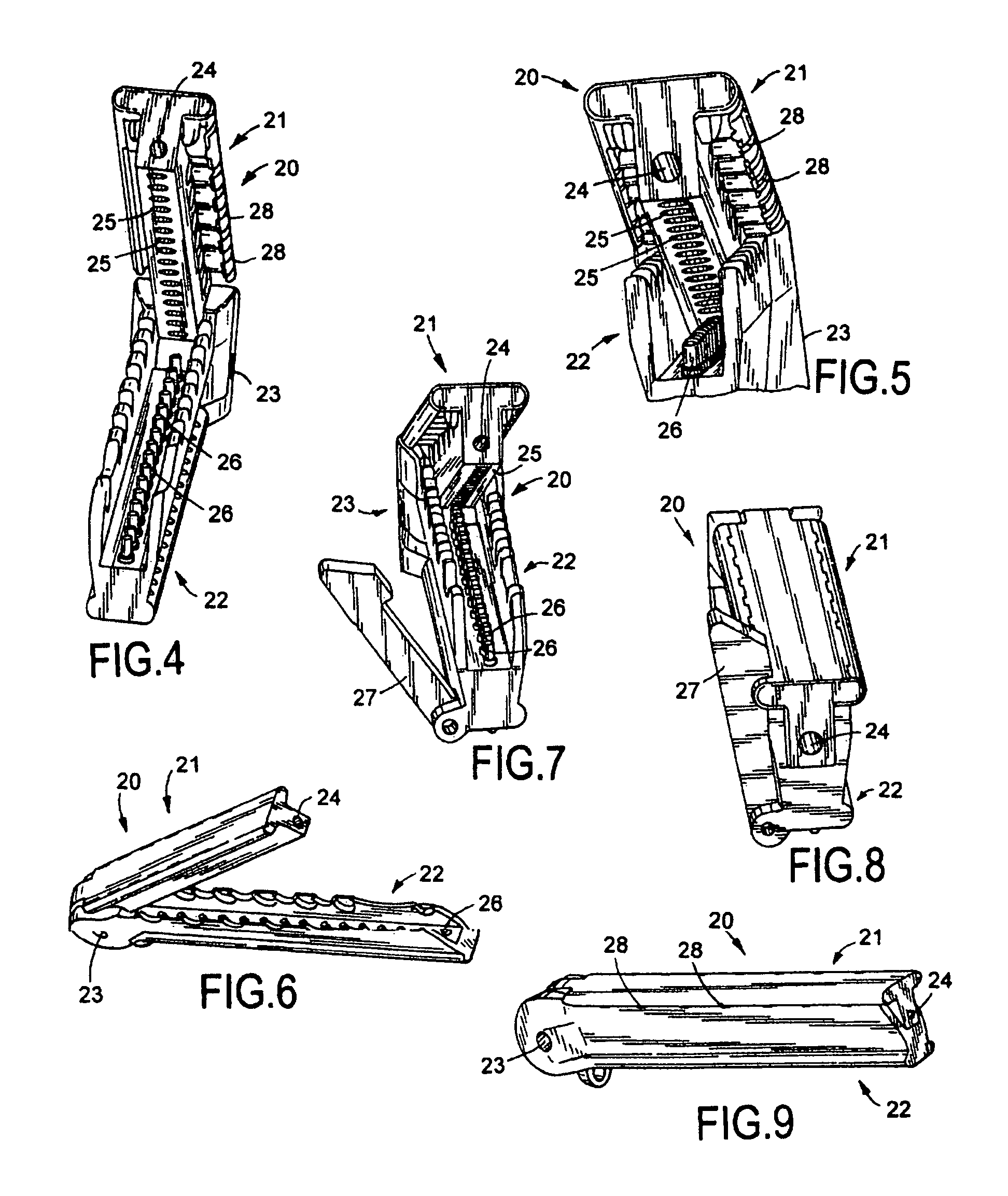
[0046]Referring to FIGS. 4-9, connector assembly embodiment 20 shows a hinged two-piece connector having a top body 21, a bottom body 22, and a hinge 23 disposed perpendicular to the connector's contact pins 26. The contact pins 26 are either spring-loaded pins or ball bearings, which may be formed of stainless steel, platinum, a platinum alloy, or the like. The hinge 23 having a dowel is shown positioned perpendicular to the length of the inline connector and perpendicular to the spring-loaded pins 26 disposed upwardly in the bottom portion 22 of the connector 20. The dowel may be a screw that threads into one side of the connector, a dowel with a recess for a pin, or an e-clip. The hinge 23 may be a press fit pin that bottoms out and is sealed in with another part or potted into place.

[0047]The inline connector top 21 of connector assembly 20 is shown having a single long hole or bore 24 in which the inline tail runs the length and terminates near the end of the top 21. The connec...

embodiment 30

[0052]Referring to FIGS. 10-15, connector assembly embodiment 30 is shown having a top body 31, a bottom body 32 and a hinge 33 with a dowel which is parallel to the connector pins 36 extending upwardly form the bottom body portion 32 of the connector assembly 30. The dowel may be a screw that threads into one side of the connector, a dowel with a recess for a pin, or an e-clip. The hinge 33 may be a press fit pin with bottoms out and is sealed in with another part or potted into place. The hinge 33 is spring loaded so that the two pieces 31, 32 can create vertical space between the two pieces for swinging the two pieces into a closed position. This allows for the convex and concave triangular locking mechanism 37 on the end of the connector pieces to mate together and to lock the unit into place.

[0053]The inline connector top 31 of connector assembly 30 is shown having a single long hole or bore 34 in which the inline tail runs the length and terminates near the end of the connecto...


PUM


Abstract

Improved electrode assemblies for recording and stimulation. Cortical and depth electrode structures are provided as well as inline interconnection systems. Methods of manufacture are further taught to provide enhanced surfaces for cortical electrodes. The inline interconnection systems include connector assembly embodiments for electrode leads which have structure providing ease of EEG recording as well as stimulation.

Description

[0001]This Application claims the benefit of U.S. Provisional Patent Application Ser. No. 61 / 227,928, filed on Oct. 1, 2009.BACKGROUND OF THE INVENTION[0002]The present invention relates generally to improved electrode assemblies for recording and stimulation. Particularly, this invention relates to improved electrode assembly structures, their use and method of manufacture. More particularly, the invention relates to improved cortical and depth electrode assemblies and related inline interconnection systems.[0003]Cortical and depth electrodes are used for monitoring recordable electrical brain activity or electroencephalograph (EEG) signals when less invasive methods do not provide the electrophysiology data necessary. The electrode recording is performed directly on the surgically exposed brain and is necessary when the seizure focus is too small and / or too deep within the brain to produce a recordable EEG signal.[0004]An adaptation of the procedure for the placement of cortical o...

Claims


Application Information

Patent Timeline
IPC IPC(8): H01R9/22A61B5/0478
CPCA61B5/04004A61B5/0478H01R4/01H01R13/6275A61N1/0531A61N1/0534H01R12/88H01R13/24H01R24/58H01R2107/00H01R2201/12A61B2562/225A61B5/291A61B5/30
Inventor OSA, BENJAMINCAILLE, ERICTALBOTT, CHARLESCOPLEY, JOSEPHIVERSEN, ALFRED
Owner PMT
Why Eureka
Try Eureka