
Cross flange seal for a pressure vessel, especially for a turbomachine casing

a technology of cross flange seal and pressure vessel, which is applied in the direction of sealing, machines/engines, cable terminations, etc., can solve the problems of difficult turbomachine overhaul, difficult to take apart the casing, and easy leakage of the seal by bolt, so as to achieve advantageous sealing action and increase the thermal volumetric expansion

Inactive Publication Date: 2013-05-14
ANSALDO ENERGIA SWITZERLAND AG
View PDF18 Cites 14 Cited by
  • Summary
  • Abstract
  • Description
  • Claims
  • Application Information

AI Technical Summary

Benefits of technology

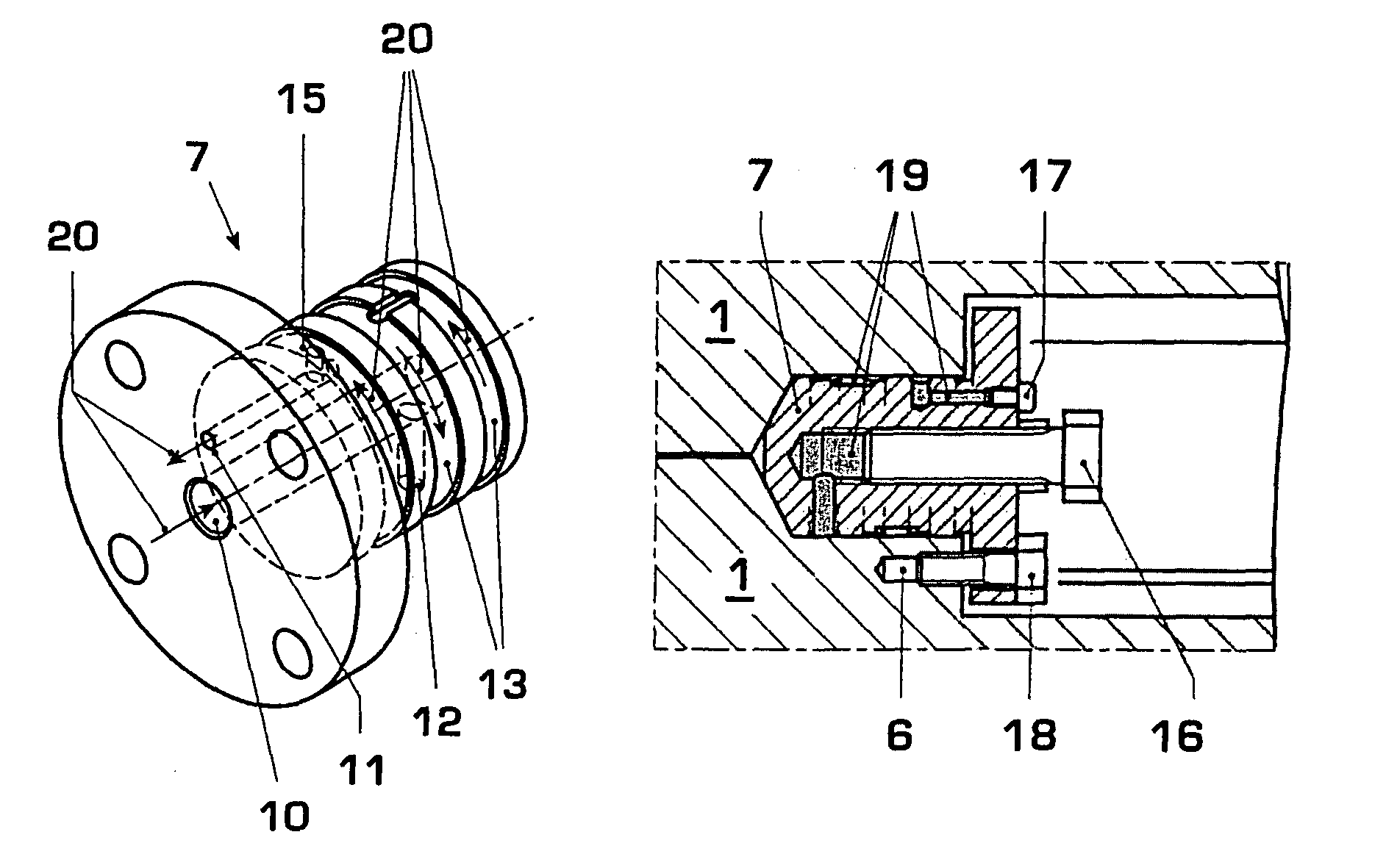
The invention is a sealing plug used in a gas turbine machine. The plug is embedded in an elastic sealing compound under an overpressure, which helps to compensate for thermal distortions without compromising the sealing integrity. The sealing compound is poured into the plug and then forced through passages inside the plug to the sealing chambers. The plug flange is fastened on the casing shell sections to secure the plug in place. The invention also allows for easy non-destructive removal and reuse of the plug without requiring mechanical reworking on the plug seat or plug.

Problems solved by technology

At the contact point of the three or more adjoining casing shell sections, small disturbances in the required geometry, as, for example, they arise as a result of damage to the flange edges during assembly of the mostly heavy casing shell sections, are practically unavoidable, which, with the high pressures which occur inside a turbomachine, inevitably leads to leaks.
All these known solution proposals, however, have disadvantages which counteract a reliable, maintenance-friendly, i.e. easily disassemblable and reassemblable, sealing of the cross flange:1. The sealing of a cross flange by means of a bolt does not meet the requirement for a reliable, maintenance-friendly seal:The bolt has to be replaced during overhauls of the turbomachine, depending upon how far wear and corrosion have impaired its durability.Since bolt and bolt seat as a rule are damaged when fitting and removing the bolt, a reworking, i.e. a reboring of the bolt seat, is necessary.
At the same time, a new, larger bolt is required.During thermal distortions of the casing, the seal by means of a bolt is prone to leaks, since the bolt has practically no elastic deformation in order to compensate distortions of the casing.2. The sealing of a cross flange by welding:Welding of the casing shell sections in the intersection region of the parting joints is indeed possible, however the taking apart of the casing becomes more difficult and overhauling of the turbomachine becomes more difficult as a result.
Furthermore, reworking of the casing shell sections and their rewelding is necessary.3. Sealing by means of a flange in the intersection region of the parting joints:It is disadvantageous in this form of sealing that the seating face on the casing shell sections is susceptible to scratches and impact points, as they can easily arise during assembly of the mostly heavy casing shell sections.
During thermal distortions or a displacement of the casing shell sections in a direction perpendicular to the flange plane, the sealing integrity is no longer ensured, so that the sealing face has to be reworked.

Method used


Image

  • Cross flange seal for a pressure vessel, especially for a turbomachine casing
  • Cross flange seal for a pressure vessel, especially for a turbomachine casing
  • Cross flange seal for a pressure vessel, especially for a turbomachine casing

Examples


Embodiment Construction

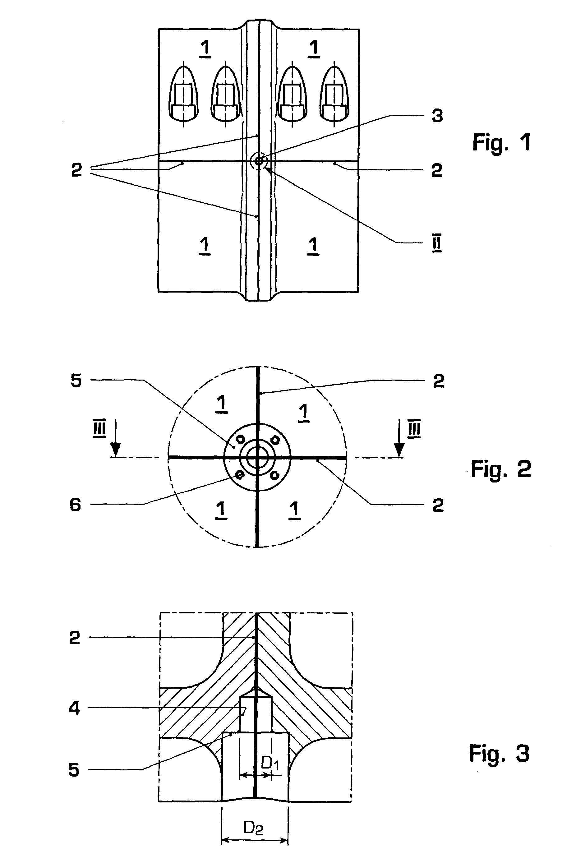
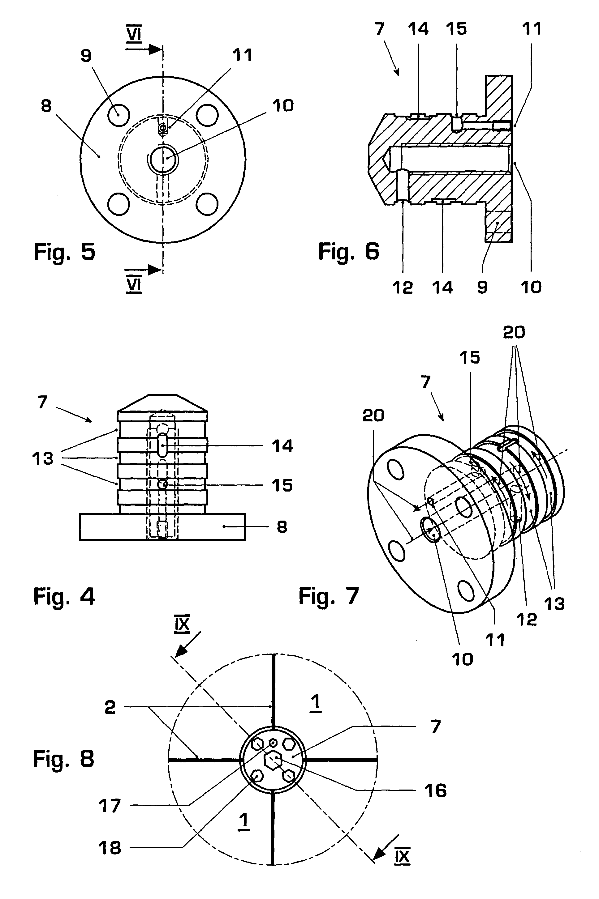
[0038]The pressure casing according to the invention, which is partially shown in FIGS. 1 to 3, exemplarily comprises four casing shell sections (1), which are preferably screwed together in a gastight manner along their parting joints (2). Since in a turbomachine, like, for example, a gas turbine, steam turbine, supercharger or compressor, the inner space generally has a high overpressure in relation to the outer space, the intersection region (3) of the parting joints (2) cannot be reliably sealed without additional measures. In order to reliably prevent the escape of steam from the intersection region (3) of the parting joints (2), the intersection region (3) of the parting joints (2) is sealed by means of an inserted plug (7). This plug (7), as shown in FIGS. 4 to 11, has a system of holes (10, 11, 12, 15) and passages (13, 14) in its interior, through which a permanently elastic sealing compound (19) is pressed into the interspace between plug (7) and casing shell sections (1)....


PUM

PropertyMeasurementUnit
circumferenceaaaaaaaaaa
pressureaaaaaaaaaa
pressure-resistantaaaaaaaaaa

Abstract

The invention relates to a pressure vessel for a machine, especially a turbomachine, which comprises at least 3 casing shell sections, wherein the intersection region of the parting joints is sealed off by a plug which in its interior has a system of holes and passages through which a sealing compound is pressed into the region between plug and casing shell sections, so that after its setting, an elastic, leakproof and non-destructively disassemblable sealing of the intersection region of the parting joints is created. The plug can be fastened on the casing shell sections by means of an integrated flange.

Description

TECHNICAL FIELD[0001]The invention relates to a pressure casing for a machine, especially for a turbomachine, which casing comprises a plurality of casing shell sections which are interconnected in a gastight manner.BACKGROUND OF THE INVENTION[0002]In such a pressure casing, the casing shell sections have contact faces, which customarily are pressed against each other by means of a respective threaded connection outside the sealing zone, so that so-called parting joints are created between adjacent casing shell sections.[0003]If three or more casing shell sections are to be interconnected at the same time, as exemplarily shown in FIG. 1 with four casing shell sections, then the intersection region of the parting joints, the so-called cross joints, cannot be reliably sealed without additional measures. At the contact point of the three or more adjoining casing shell sections, small disturbances in the required geometry, as, for example, they arise as a result of damage to the flange ...

Claims


Application Information

Patent Timeline
Patent Type & Authority Patents(United States)
IPC IPC(8): B65D53/06B65D51/16
CPCF01D11/00F01D11/005F01D25/265F16J15/062F16J15/14F16L55/11F16L55/1108
Inventor NORMAN, DARRAN-LEEMATAN, MLADEN
Owner ANSALDO ENERGIA SWITZERLAND AG
Learn More