Color measuring device

a color measuring and color technology, applied in the field can solve the problems of affecting the measurement, affecting the accuracy of color measurement, and failure of color measuring devices, and achieve the effect of compact and cost-effective design

Active Publication Date: 2013-05-14
X RITE SWITZERLAND
View PDF10 Cites 11 Cited by
  • Summary
  • Abstract
  • Description
  • Claims
  • Application Information

AI Technical Summary

Benefits of technology

[0007]Based on the theoretical thinking behind the invention, the lighting arrangement has a lamp ring with three or more lamp groups mutually offset from one another at an angle, preferably equidistantly, around 360°, each comprising at least one light source for illuminating the measurement field at an angle of incidence within a defined range relative to the normal with respect to the measurement field. The pick-up arrangement has a photoelectric converter arrangement in the form of an imaging sensor, in particular a digital camera, which creates an image of the measured measurement field made up of image pixels. The electronic circuit is designed to switch the light sources of the lamp groups of the lighting arrangement on selectively, and the imaging sensor creates a separate image of the measurement field for one or more individually switched-on light source(s) and forwards the associated measurement values of the individual image pixels as image data to the electronic circuit. The measuring technique based on this design also enables measurement fields containing several colors to be measured and enables them to be illuminated from different spatial angles so that in the case of measurement fields with a textured surface, the measurement values can be subjected to additional processing for the purpose of correcting and / or eliminating the effects of interference caused by the texture.
[0009]It is of particular practical advantage if every lamp group has one or more UV-light sources irradiating specifically in the range of 360-400 nm. This will also enable measurement objects containing brighteners to be correctly measured.
[0010]It is of more particular advantage to use light-emitting diodes as light sources, which are preferably disposed on a common circuit board. This makes for a compact and cost-effective design of the lighting arrangement and hence the measuring unit as a whole.
[0011]In one particularly advantageous embodiment of the color measuring device proposed by the invention, the electronic circuit is designed to run a masking operation on the image data based on specific criteria, in which case image data derived from image pixels satisfying the criteria is excluded from subsequent processing. Those image pixels which have a brightness value that is higher or lower than the total image pixels of the measurement field by a threshold value or image pixels which are gloss pixels or shadow pixels are preferably masked or excluded. This already eliminates a significant amount of factors which cause interference.

Problems solved by technology

However, when it comes to measuring or detecting the colors of measurement objects with a structured surface (textures), these color measuring devices usually fail because the measurement results can be distorted by the surface structure of the measurement object.
Depending on how pronounced the surface texture is, the illuminating light can create gloss effects and / or shadowing effects which adversely affect the measurement and lead to an incorrect color result.
Another problem arises if a measurement object has two or more colors at the measuring point of interest and the intention is to determine all the colors.
This objective can not usually be achieved at all with known, conventional color measuring devices.

Method used


Image

  • Color measuring device
  • Color measuring device
  • Color measuring device

Examples


Embodiment Construction

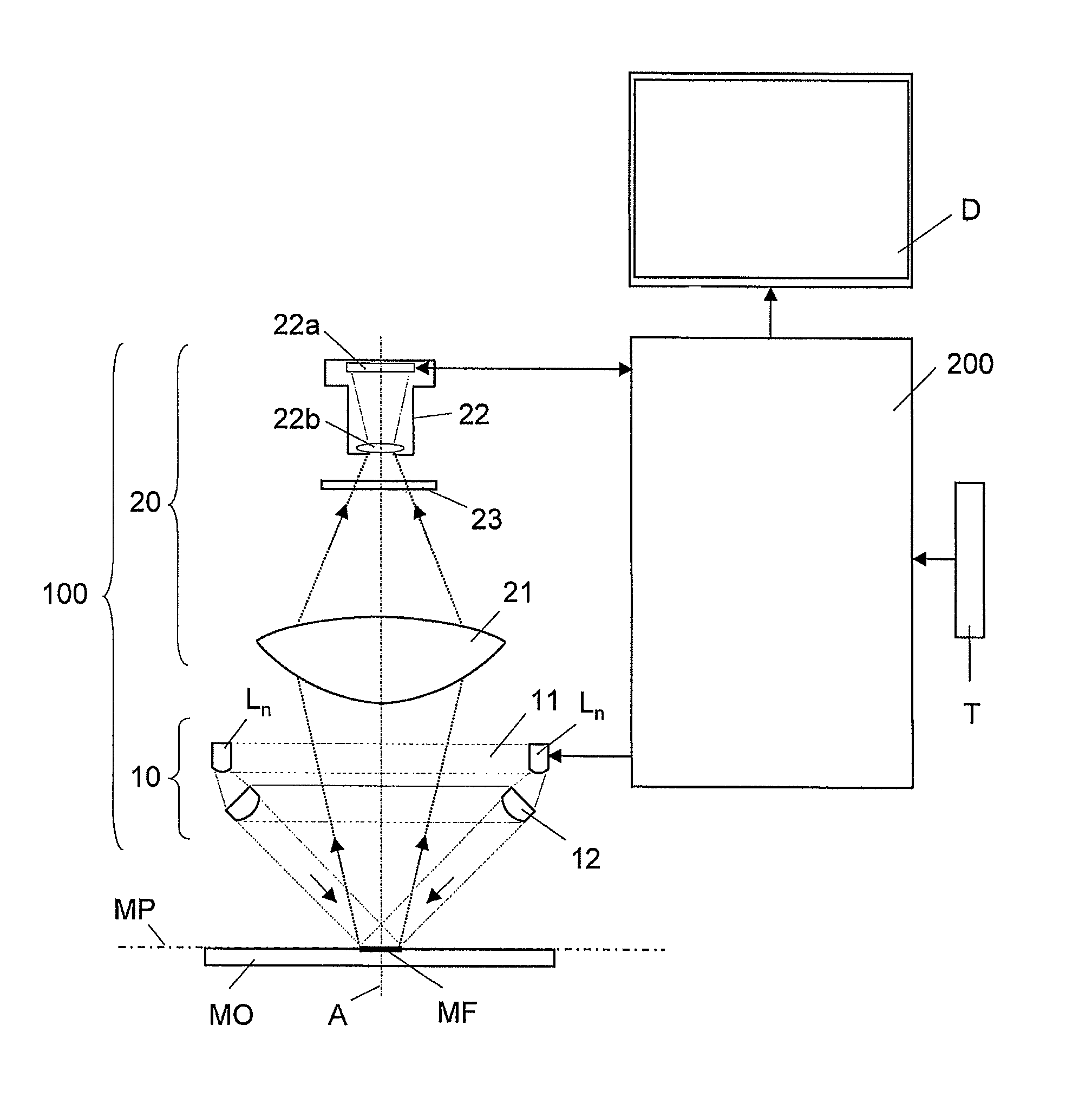
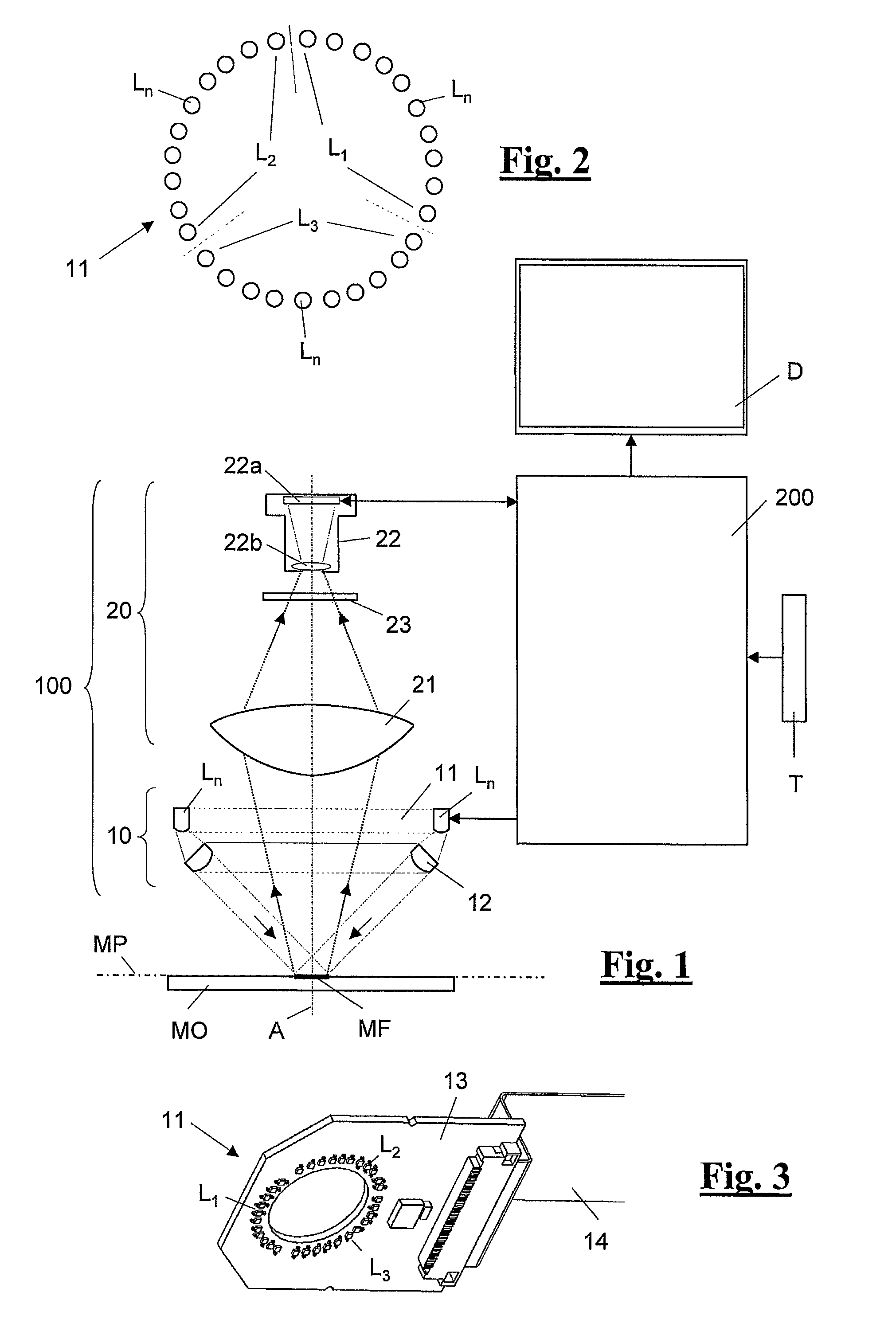
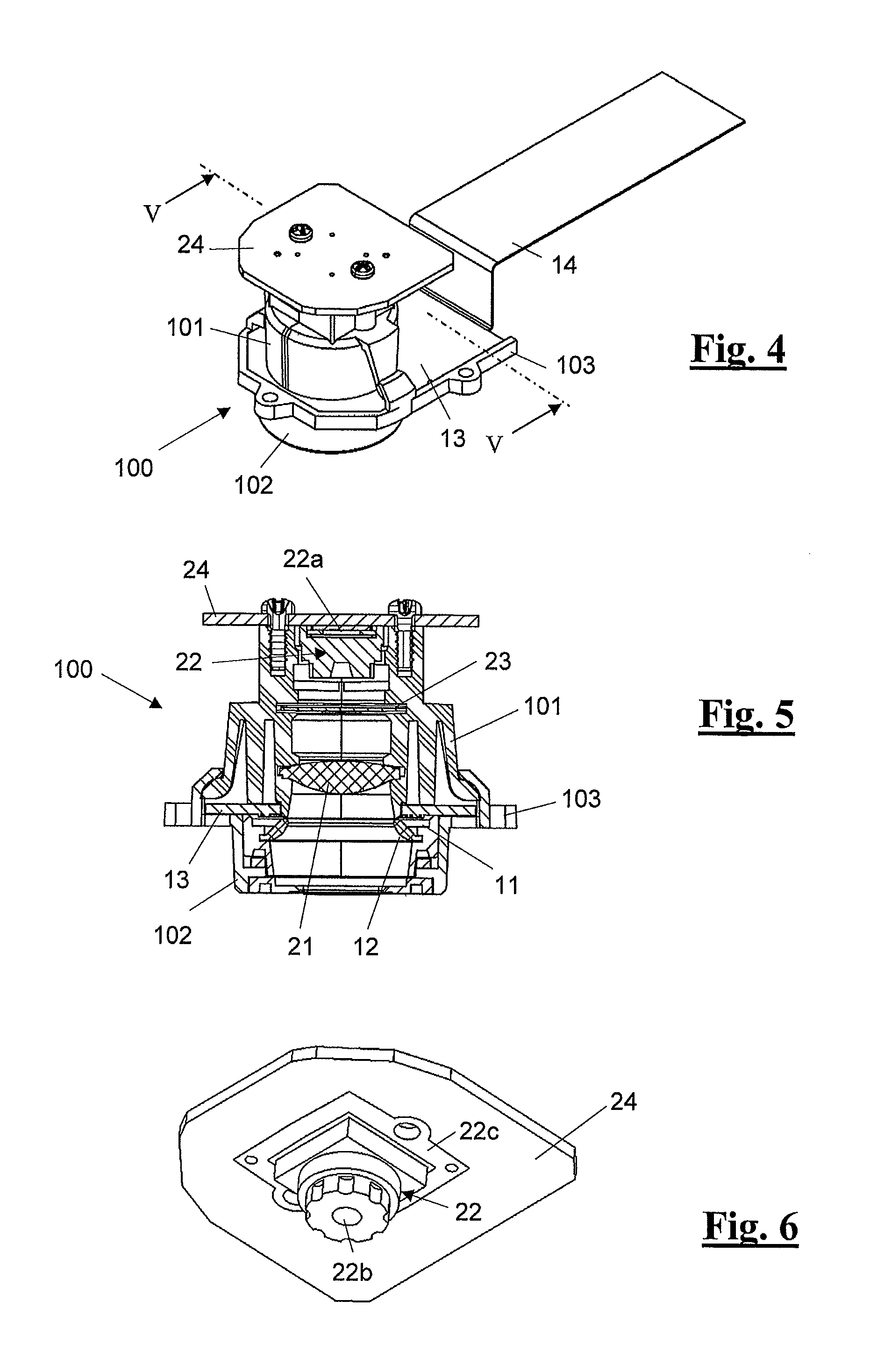
[0027]The color measuring device proposed by the invention is preferably a hand-held measuring device, and all the functional components are housed in or on an elongate, essentially rectangular housing G with rounded edges (FIG. 10). Disposed on the bottom face of the housing G is a measurement window F through which the measurement object is measured. Disposed on the top face of the housing G is a display D with graphics capability and control keys T (FIG. 9). Disposed in the interior of the housing G and overlapping the measurement window F is a measuring unit denoted as a whole by reference 100. Also disposed in the interior of the housing G is a digital, computer-based electronic circuit 200 for controlling the color measuring device and processing the measurement values (FIG. 9). The electronic circuit 200 cooperates with the measuring unit 100 and control keys T as well as the display D and contains the usual components of a digital controller, namely a processor, working, dat...


PUM

PropertyMeasurementUnit
angleaaaaaaaaaa
angleaaaaaaaaaa
angle of incidenceaaaaaaaaaa

Abstract

A color measuring device includes a lighting arrangement for a measurement field of a measurement object to be measured, a pick-up arrangement for detecting the measurement light reflected back from the measurement field and for converting it into corresponding electric signals, an electronic circuit for controlling operation of the color measuring device and for processing and evaluating the electric signals, and a display for displaying measurement results. The lighting arrangement has a lamp ring with three identical lamp groups for illuminating the measurement field from a predefined range of angles of incidence. The pick-up arrangement has a digital camera which creates an image of the measured measurement field. The electronic circuit is designed to switch the light sources of the lamp groups on sequentially, and the camera creates a separate image of the measurement field for every switched-on light source.

Description

FIELD OF THE INVENTION[0001]The invention relates to a device for measuring the color of a measurement field of a measurement object to be measured.BACKGROUND OF THE INVENTION[0002]Known color measuring devices usually contain an arrangement for illuminating the measurement object to be measured, a pick-up arrangement for detecting the measurement light reflected back from the measurement object and converting the detected measurement light into corresponding electric signals, and an electronic system for evaluating the electric signals and for controlling the operating sequence of the measuring device. The illuminating arrangement may be designed to generate white light or colored light. The converter arrangement may comprise a number of color filters or dispersive elements, e.g. a diffraction grating, for splitting the measurement light into different wavelength ranges. Photodiodes or CCD converter systems may be provided for the actual conversion into signals.[0003]These known co...

Claims


Application Information

Patent Timeline
Patent Type & Authority Patents(United States)
IPC IPC(8): G01N21/25
CPCG01J3/02G01J3/0278G01J3/10G01J3/50G01J3/501
Inventor WEGMULLER, MARKFRICK, BEAT
Owner X RITE SWITZERLAND
Why Eureka
Try Eureka