Method and device for monitoring a radio-frequency transmitter device in a magnetic resonance tomography system

a radio-frequency transmitter and magnetic resonance tomography technology, applied in the field of monitoring a radio-frequency transmitter device of a magnetic resonance tomography system, can solve the problems of limited functioning of radio-frequency transmitter devices, and achieve the effect of avoiding the peak loading of patients

Active Publication Date: 2013-05-14
SIEMENS HEALTHCARE GMBH
View PDF5 Cites 11 Cited by
  • Summary
  • Abstract
  • Description
  • Claims
  • Application Information

AI Technical Summary

Benefits of technology

[0007]An object of the present invention is to provide a method and device for monitoring a radio-frequency transmit device that reliably prevent the radio-frequency power absorbed by the examination subject from exceeding a prespecified threshold value, and while still enabling the exploitation of the given boundary values as far as possible, even in a transmitter antenna system having a multiplicity of separately controllable transmit channels.
[0011]Using the method according to the present invention, it is possible to determine the power deposited in the examination subject relatively precisely, and thus to optimally exploit the specified boundary values even in a multichannel transmit antenna system. This method can be implemented online during the measurement; i.e., using this method each of the radio-frequency pulses sent out can be measured precisely during the measurement. In principle, however, this method can also be used ahead of time during a simulation in order to determine, even before the measurement, whether a measurement can be carried out using the planned transmit parameters without expecting boundary values to be exceeded. During such a “look-ahead” monitoring, a limitation of the functioning of the radio-frequency transmit device is to be understood as meaning that, for example, a magnetic resonance measurement that is to be carried out using transmit parameters in which a boundary monitoring value would be exceeded is prevented or is modified, and for example the operator is informed of this via a suitable warning message. That is, the monitoring of the radio-frequency transmit device can take place not only by a direct monitoring signal, but also indirectly through action on a transmit protocol for controlling the magnetic resonance installation or the like. In particular, it is also possible to carry out both such a look-ahead monitoring before the start of a measurement, using the method according to the present invention, and also to additionally use this method to monitor the maintenance of the boundary values online during the measurements.
[0025]In a preferred embodiment, each of the radio-frequency power amplifiers that emit the radio-frequency pulses via the respective transmit channels can additionally be regulated on the basis of the voltage values determined using the directional couplers. That is, the voltage measurement values of the directional couplers can be used as actual values that are brought into agreement with the target values that correspond to the required signals. In this way, a very simple, more precise controlling of the radio-frequency power amplifiers is also possible.
[0027]Preferably, various monitoring values are taken into account via different sliding time windows; for example, a short-time monitoring value via a window ten seconds in length and a long-time monitoring value via a window 360 seconds in length. In this way, it can be ensured that on the one hand a peak loading of the patient is avoided, while on the other hand a radiation load does not occur that is too high overall but that always remains just under the peak boundary values.

Problems solved by technology

Based on a large number of determined radio-frequency power values, a number of monitoring values are then formed, and the radio-frequency transmitter device is limited in its functioning when a monitoring value reaches or exceeds a prespecified boundary monitoring value.

Method used


Image

  • Method and device for monitoring a radio-frequency transmitter device in a magnetic resonance tomography system
  • Method and device for monitoring a radio-frequency transmitter device in a magnetic resonance tomography system
  • Method and device for monitoring a radio-frequency transmitter device in a magnetic resonance tomography system

Examples


Embodiment Construction

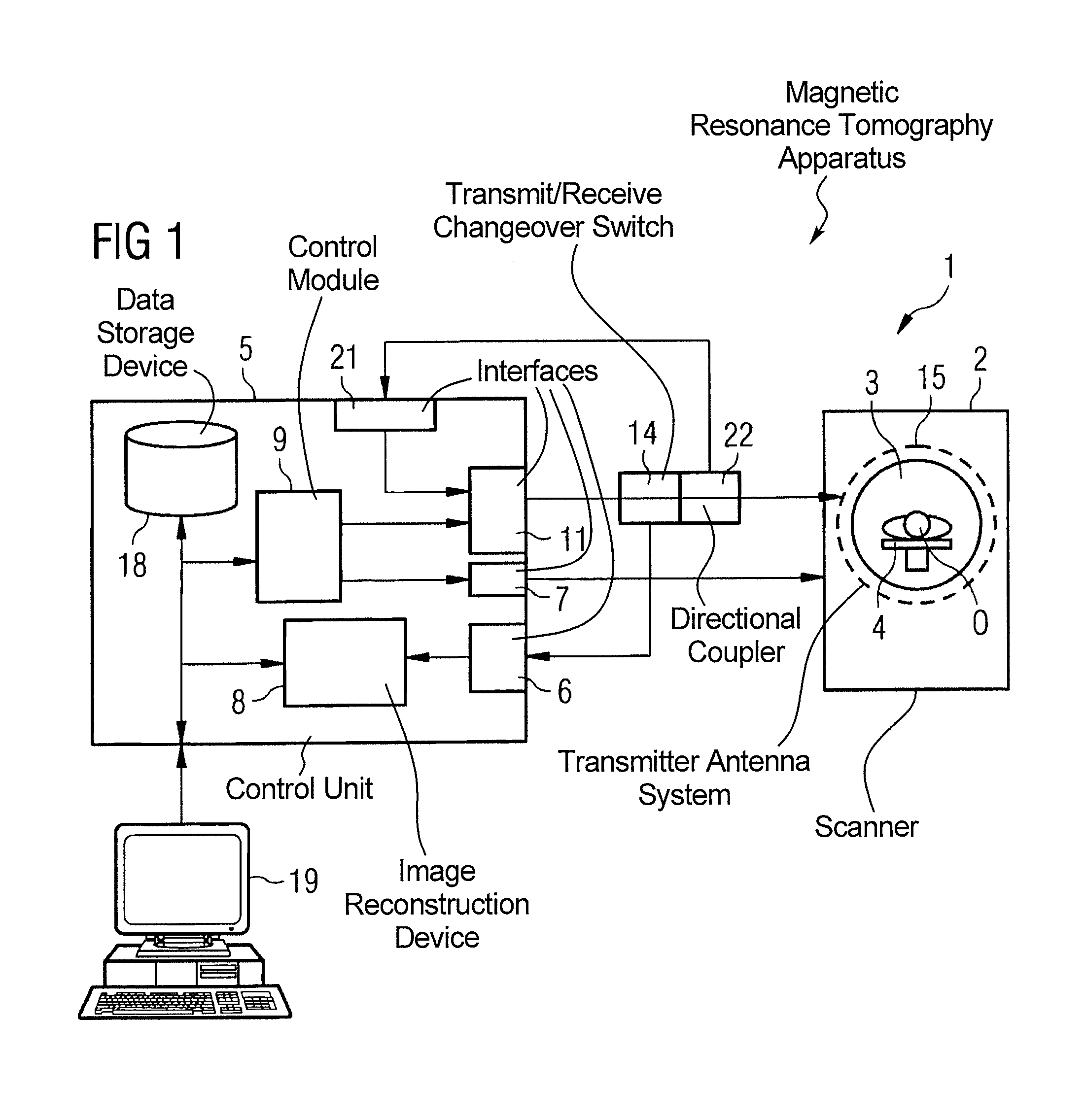
[0034]A basic part of the magnetic resonance tomography system 1 shown in highly schematic form in FIG. 1 is the scanner or tomograph 2 that carries out the actual measurements. In this scanner 2 there is situated a measurement space 3, generally called a patient tunnel, in which a patient or subject of examination O can be positioned on a patient bed 4. Here, the scanner 2 has, as a transmit antenna system 15, a whole-body coil 15 having a number of separately controllable transmitter channels in order to enable the formation of arbitrary field distributions in measurement space 3. For example, this can be what is known as a birdcage coil that has N conductor rods that are independently controllable and are situated parallel to one another on a cylinder surface around measurement space 3 and are coupled to one another. However, the present invention is not limited to such transmitter antenna systems. In particular, it is also not necessary that the transmit antenna system form a wh...


PUM


Abstract

In a device for monitoring a radio-frequency transmit device of a magnetic resonance system, having a transmitter antenna system that has a number of transmit channels, a reference scattering parameter matrix of the transmitter antenna system is determined in the unloaded state with no subject present, and a subject-specific scattering parameter matrix of the transmitter antenna system is determined in a state loaded with the subject. time-dependent transmitter amplitude vectors are determined that represent the radio-frequency voltage amplitudes on the individual transmit channels. From the subject-specific scattering parameter matrix, the reference scattering parameter matrix, and the transmit amplitude vectors, radio-frequency power values absorbed at particular transmit times in the subject are determined, from which monitoring values are formed that, when reached, cause operation of the radio-frequency transmit device to be limited during acquisition of magnetic resonance data.

Description

BACKGROUND OF THE INVENTION[0001]1. Field of the Invention[0002]The present invention relates to a method for monitoring a radio-frequency transmitter device of a magnetic resonance tomography system, having a transmit antenna system that has a multiplicity of transmitter channels, during a magnetic resonance measurement of an examination subject. In addition, the present invention relates to a radio-frequency transmit device for such a magnetic resonance tomography system, to a radio-frequency monitoring device for such a radio-frequency transmit device, and to a magnetic resonance tomography system having such a radio-frequency transmitter device.[0003]2. Description of the Prior Art[0004]An imaging using a magnetic resonance tomography system essentially takes place in three steps. First, a strong, stable, homogenous magnetic field, and thus a stable orientation of the protons in the relevant body region, is produced around the body region. This stable orientation is then modifie...

Claims


Application Information

Patent Timeline
Patent Type & Authority Patents(United States)
IPC IPC(8): A61B5/05
CPCG01R33/288G01R33/34076G01R33/3415G01R33/48G01R33/3628
Inventor NISTLER, JUERGENVESTER, MARKUS
Owner SIEMENS HEALTHCARE GMBH
Why Eureka
Try Eureka