Differential voltage sensing method

a differential voltage and sensing technology, applied in the field ofdifferential voltage sensing system, can solve the problems of small biopotential signal acquired from the human body, easy interference, electrical signal is easily subject to distortion

Active Publication Date: 2013-05-14
IND TECH RES INST
View PDF29 Cites 2 Cited by
  • Summary
  • Abstract
  • Description
  • Claims
  • Application Information

AI Technical Summary

Problems solved by technology

The bio-potential signal acquired from the human body is quite small, and is easily subject to interference from the external environment or from other bio-potential signals from the test subject.
However, the common mode noise signals cannot be eliminated when the input impedances of the differential voltage sensing system are not equal, and without elimination of the common mode noise signals the electrical signals are easily subject to distortion because of the interference noise.
In particular, effective electrical signals cannot be captured from multi-pole EEG or multi-lead ECG signals when defective electrodes are present.
However, since the input impedance balancing is achieved by varying the conversion characteristics of the circuit, an oscillatory noise is generated by such arrangement.

Method used


Image

  • Differential voltage sensing method
  • Differential voltage sensing method
  • Differential voltage sensing method

Examples


Embodiment Construction

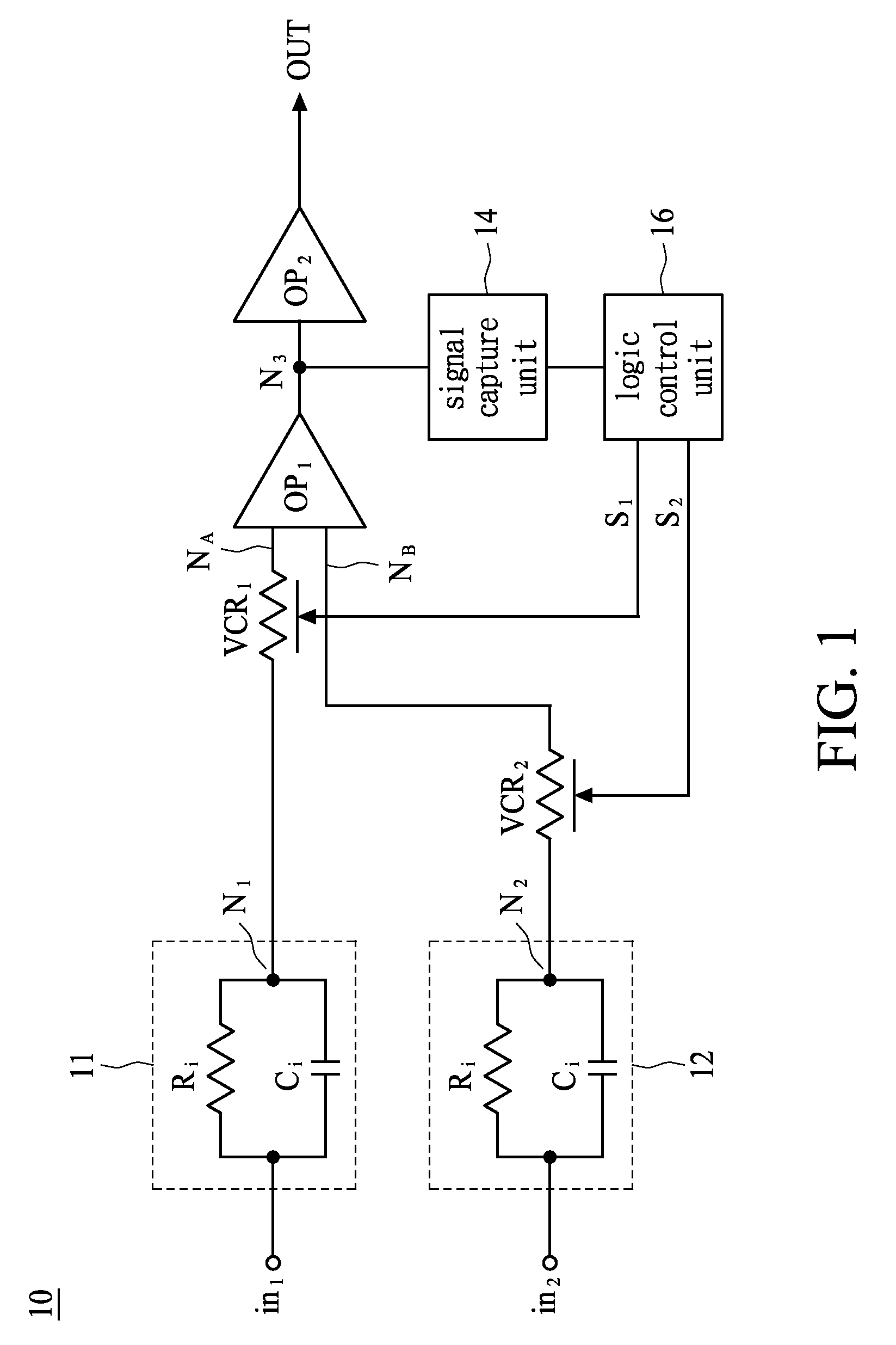
[0017]FIG. 1 is a block diagram of a differential voltage sensing system 10 in accordance with an exemplary embodiment. The differential voltage sensing system 10 comprises first and second electrode interfaces 11 and 12, first and second variable resistors VCR1, VCR2, first and second amplifying circuits OP1 and OP2, a signal capture unit 14, and a logic control unit 16. As shown in FIG. 1, the first electrode interface 11 is connected between an input node in1 and a node N1, while the second electrode interface 12 is connected between an input node in2 and a node N2, wherein the input nodes in1 and in2 are connected to two different positions of a single bio-potential source. The first and second electrode interfaces 11 and 12 are configured to detect bio-potential signals, such as ECG, EOG, EMG, or EOG signals, from a test subject, wherein these bio-potential signals have a common mode signal voltage level and a differential mode signal voltage level. Each of the electrode interf...


PUM


Abstract

A differential voltage sensing method for achieving input impedance matching comprises the steps of: providing a first bio-potential signal to a first variable resistor for generating a first signal; providing a second bio-potential signal to a second variable resistor for generating a second signal; differentially amplifying first and second signals for generating a third signal; selecting an operation band of the third signal for generating first and second logic signals; and dynamically adjusting one of the impedances of the first and second variable resistors according to the first and second logic signals, wherein each of the first and second bio-potential signals has a common signal voltage level and a differential signal voltage level.

Description

BACKGROUND[0001]1. Technical Field[0002]This disclosure relates to a differential voltage sensing system and a method for achieving input impedance matching, and, in particular, to a differential voltage sensing system and method for sensing bio-potential signals.[0003]2. Description of the Related Art[0004]With the increased focus on personal health among people in recent years, and with the increasing life expectancy of the global population, applications for measuring and monitoring bio-potential signals such as the electrocardiogram (ECG) signal, the electroencephalogram (EEG) signal, the electromyogram (EMG) signal, and the electrooculogram (EOG) signal are frequently required, and the related products are increasingly popular. One widely-used bio-potential measurement apparatus measures signals from the human body via external skin patch electrodes adhesively attached to the subject's skin, and monitors physiological conditions of the heart or the brain via recording and furth...

Claims


Application Information

Patent Timeline
Patent Type & Authority Patents(United States)
IPC IPC(8): A61B5/04A61B5/0402A61B5/0476A61B5/0488A61B5/05A61B5/053H03F3/45
CPCA61N1/3702A61N1/3712A61N1/3925A61N1/3937A61B5/318A61B5/369A61B5/389A61B5/398H03F3/45475H03F3/4595H03F2200/261H03F2200/411H03F2203/45544H03F2203/45591H03F2203/45594H03G1/0035
Inventor CHANG, WEN YINGCHANG, CHENG HUNGCHEN, YING JU
Owner IND TECH RES INST
Why Eureka
Try Eureka