The platform mounted to the side of crane tip is limited in useable work range because the boom blocks much of the overhead work area, as well as work on the side of the platform attached to the crane.
Also, while the prior art work platform with the centered pivot pin and rotation mechanism on the crane boom advantageously has 360-degree rotation, its pivot attached inside the basket takes up valuable platform
payload space.
Similarly, the generally U-shaped exterior support structure portion of the yoke-style platform's boom tip attachment design often obstructs the work access range of onboard personnel.
While this center-mounted rotating / pivoting prior art platform on a crane boom advantageously has 360-degree rotation, its pivot is attached inside the basket, which takes up valuable platform
payload space and also blocks overhead work access range.
Furthermore, when cranes have their booms stowed over the
chassis cab, a yoke-style platform attached to would hang too far below the boom for road-legal-travel, obstructing at least part of the driver's view of the road ahead.
Also important is that
pendulum-style gravity-leveling platform designs have an inherent negative flaw that causes them to swing and rock if
payload and people inside the platform move while the supporting crane is raised or lowered.
In addition, when the prior art platform's
brake is applied to lock the leveling, and any the onboard personnel of payload load in the platform subsequently moves to a new location, the center of gravity of the platform is also likely to change Thus, unless the personnel and / or other load are moved back to their original positions before the
brake is released to re-establish the original center of gravity, or other provisions are taken to rebalance payload and / or personnel, upon
brake release the platform will suddenly tilt out-of-level and chaotically throw the payload and personnel into the side rails of the platform, causing distress and damage.
Thus, historically during routine crane movement, a work platform's center of gravity had to be kept in line with its
pendulum plumb line, with care taken at the outset to remember the initial balance and positioning of onboard personnel and loads, as well as care taken to rebalance onboard personnel and loads before the platform is rotated out of its locked position, otherwise it will be out-of-level with unpleasant and potentially dangerous consequences.
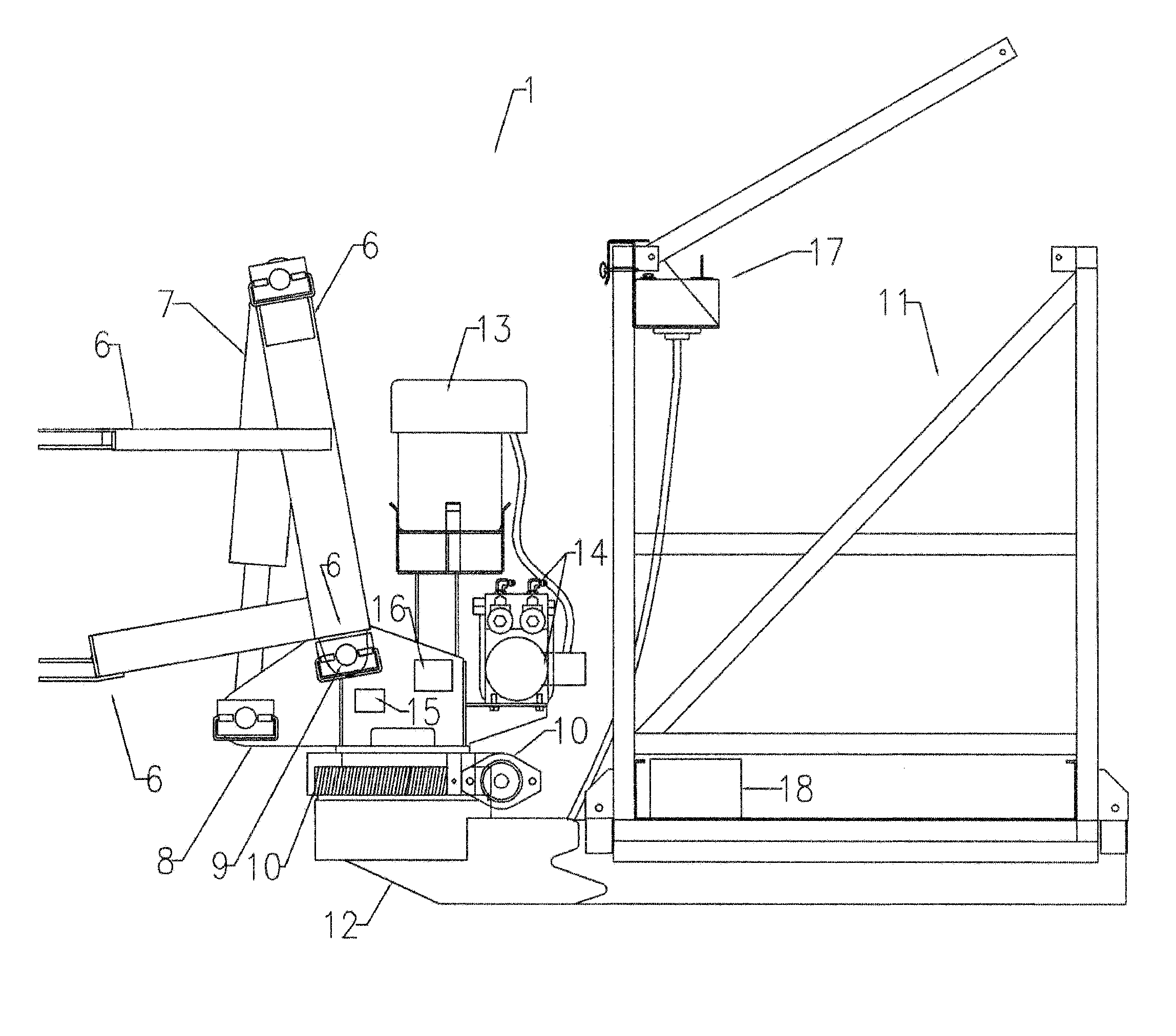
In contrast, the present invention platform has auto-powered leveling that instantly compensates for any changes in the platform's center of gravity due to repositioning movement of payload and / or personnel, and does not allow
chaotic movement to occur at elevation upon brake release.
Mobile crane boom manufacturers do not currently offer, nor are
mobile crane booms designed for, a factory-ready (or an after-market) self-contained work platform that employs, adapts, and / or otherwise incorporates modern
aerial lift features with self-platform leveling and rotation, and any attempt to do so by means other than the self-contained and self-powered work platform attachment herein would require modification to the entire
mobile crane boom
assembly to supply the associated platform with power (hydraulic or electric) for its needed platform leveling and rotational features, and would also require a new mechanically-designed platform mounting structure and
assembly.
While these work platforms and baskets have many features and mechanisms that are similar to those of the instant invention, such as powered mechanical leveling or platform rotation, these work platforms are also designed and manufactured with many dedicated / integral components that work only with their own specifically designed product, and cannot be easily adapted for other use.
Furthermore, such platforms are not self-contained, and power from the associated
truck is needed for its work platform leveling and rotation functions.
In addition, these
aerial lift boom trucks do not have a swing-jib or a boom tip designed sheave head configured for a swing-jib, and thus do not secure their platforms in position using a standard swing-jib pinning system.
This prior art design is dangerous, expensive to purchase, and not user-friendly.
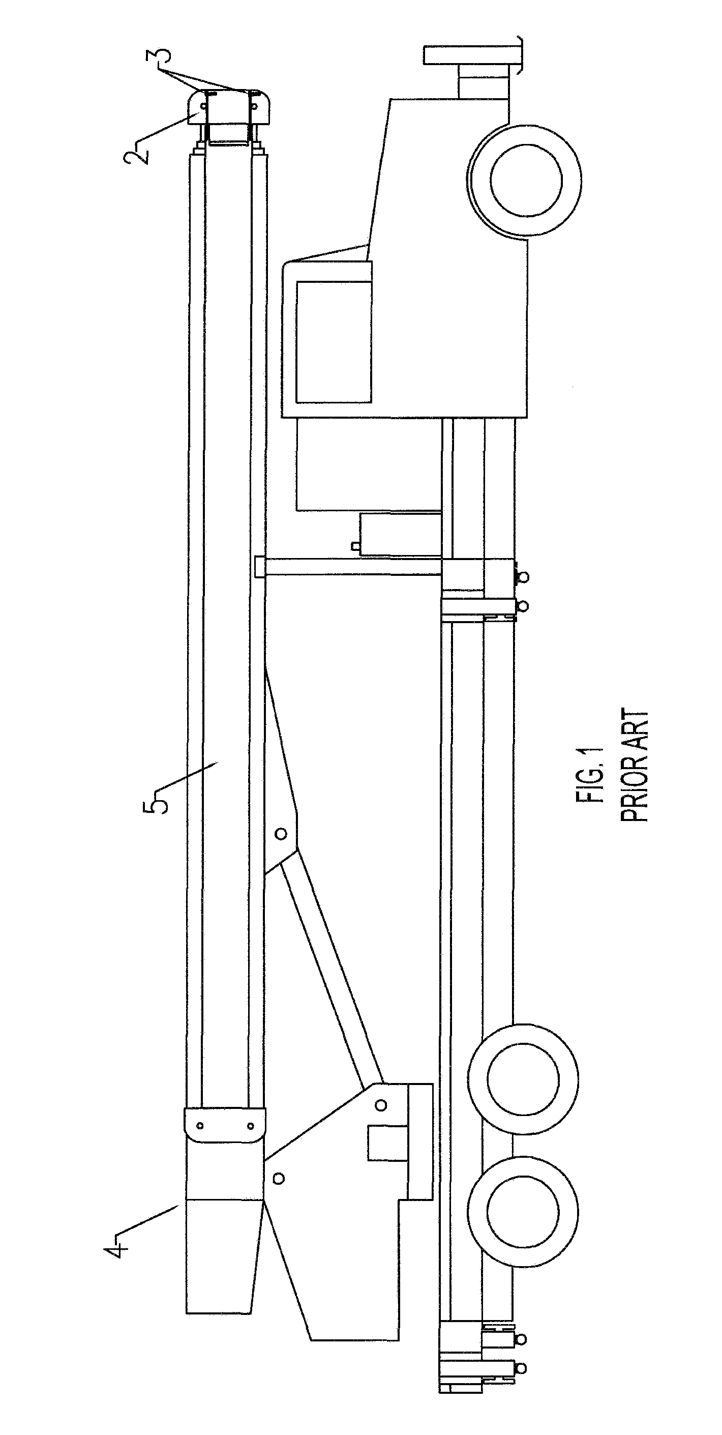
In contrast, the current designs of prior art side-mounted and yoke-mounted crane work platforms instead typically have a long
pendulum design with a low center-of-gravity configured to reduce the
chaotic rocking motion during platform elevation change that can lead to injury / damage of personnel and payload.
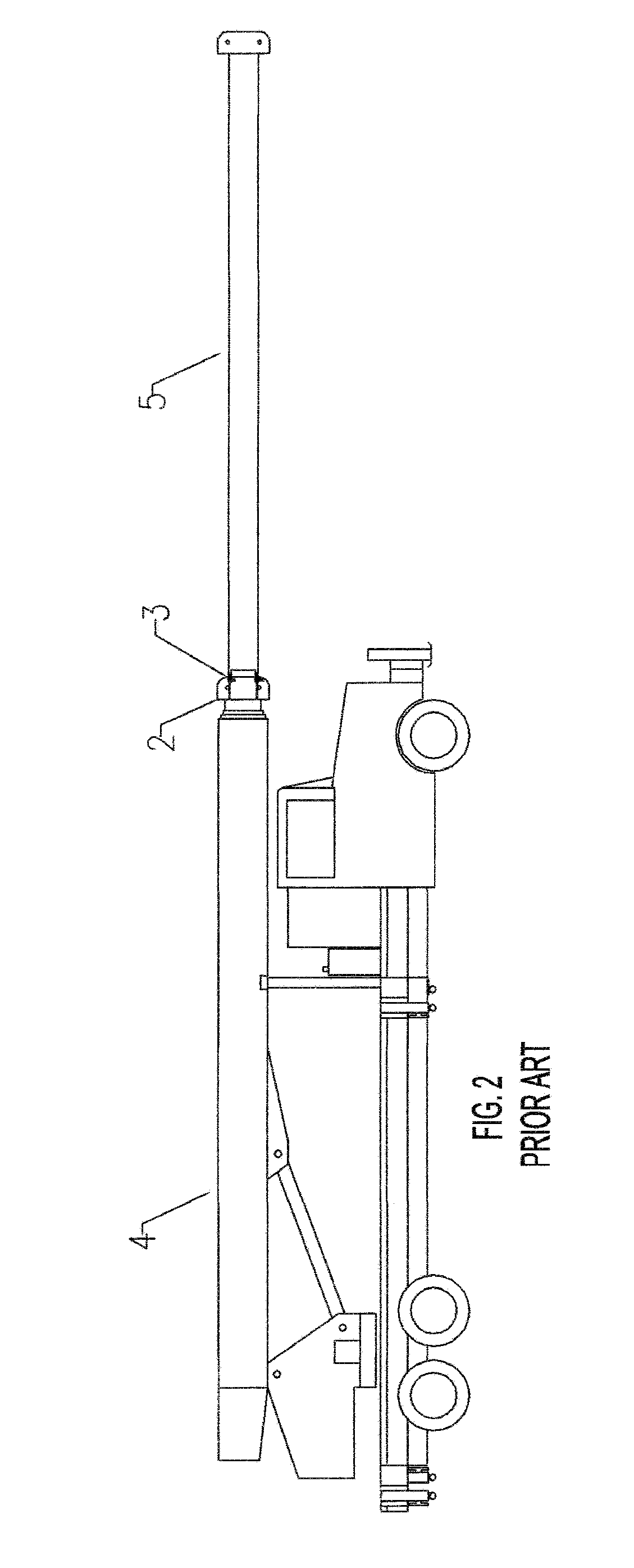
Thus, when stowed over a
chassis cab, they are usually not compact, which prevents road-legal-travel in a mounted and ready-to-use position.
While a shorter pendulum length would allow a shorter overall stowed height and the possibility of road-legal-travel, onboard personnel using such a platform would have the nearly impossible task of re-establishing a balanced position / location for people and payload before each brake release in advance of a platform elevation change, and if the needed balance is not substantially achieved,
chaotic platform rocking would ensue.
In 1983, when the Griffiths
patent application was filed, others were making and using electronic leveling sensors on work baskets / platforms, such as those available from P-Q Controls in Bristol, Conn., but these baskets / platforms did not have onboard battery power.

