Extrusion device

a technology of extrusion device and drive body, which is applied in the direction of liquid/fluent solid measurement, container, volume measurement, etc., can solve the problems of only limited maximum transmittable force, asymmetries or jams in the device section, and complicate the manipulation of the extrusion device. , to achieve the effect of simplifying the attachment of the drive body

Active Publication Date: 2013-05-21
HILTI AG
View PDF12 Cites 1 Cited by
  • Summary
  • Abstract
  • Description
  • Claims
  • Application Information

AI Technical Summary

Benefits of technology

[0009]Particularly, aspects of the present invention should improve a coupling between the lever arrangement and the extrusion rod arrangement of the extrusion device for the extrusion of material from at least two containers.
[0013]Overall, the concept of aspects of the present invention enables an improved transmission of force upon the conversion of a rotary movement of the lever arm into a linear movement of at least two drive bodies, that is two or more drive bodies, by means of an arrangement wherein each of the lever push arms acts directly on each of the drive bodies, and wherein moreover that lever body is designed in a comparatively simple manner. In addition, according to aspects of the present invention, the fork explained above has at least two fork sections and a fork trunk. The concept of the invention renders force-transmitting coupling elements, such as braces, plunger plates, or the like, redundant, because the lever body—preferably a one-piece lever body—forms the required number of lever push arms.
[0014]Even in the case of highly varying forces which are directed against the drive body from the container side, the lever arrangement is sufficiently stable on its own. It is possible to extrude materials from two or more containers without the known disadvantages of the prior art. Particularly, the lever arrangement according to the concept of aspects of the present invention does not tend to become canted or tilted. For example, essentially no torsional moments are created, such that overall an otherwise complex mounting of the parts of the lever arrangement, particularly the drive body, is substantially unnecessary and / or can be significantly simplified. The concept of aspects of the present invention enables each of the drive bodies to be directly actuated via one of the lever push arms, without a coupling element, in a particularly preferred manner.
[0021]A roller head can have a nose contour designed according to requirements for the purpose of effectively converting the rotary movement of the lever push arm into a linear movement of the drive body.
[0032]A frontal drive body is fixed on a rod upon the exertion of force on said drive body, preferably in a clamping manner and tilted in the direction of advancement. A rear drive body is fixed on a rod upon the exertion of force on said drive body, preferably in a clamping manner and tilted against the direction of advancement. The frontal drive body serves to advance the rod upon the extrusion of a material from a container, in an advantageous manner. The rear drive body preferably serves to hold the rod in position as long as a counter force of the material is being exerted, and a lever push arm is not exerting any force, i.e., when the operator has not released the lever grip.

Problems solved by technology

A particular problem arises for extrusion devices which are intended to also be suitable for the extrusion of multi-component materials from at least one container, in a special manner, that is particularly for two or more containers, in addition to the extrusion of single component materials.
A disadvantage with this configuration is the maximum transmittable force, which is only limited by a brace or a plunger plate.
By means of an insufficient guidance or excessive force, a coupling element such as a brace or a plunger plate or the like can be bent or made askew undesirably, such that asymmetries or jams can arise in the section of the device intended for manual operation.
This can significantly complicate the manipulation of the extrusion device, and can damage the extrusion device in the worst cases.

Method used


Image

  • Extrusion device
  • Extrusion device
  • Extrusion device

Examples


Embodiment Construction

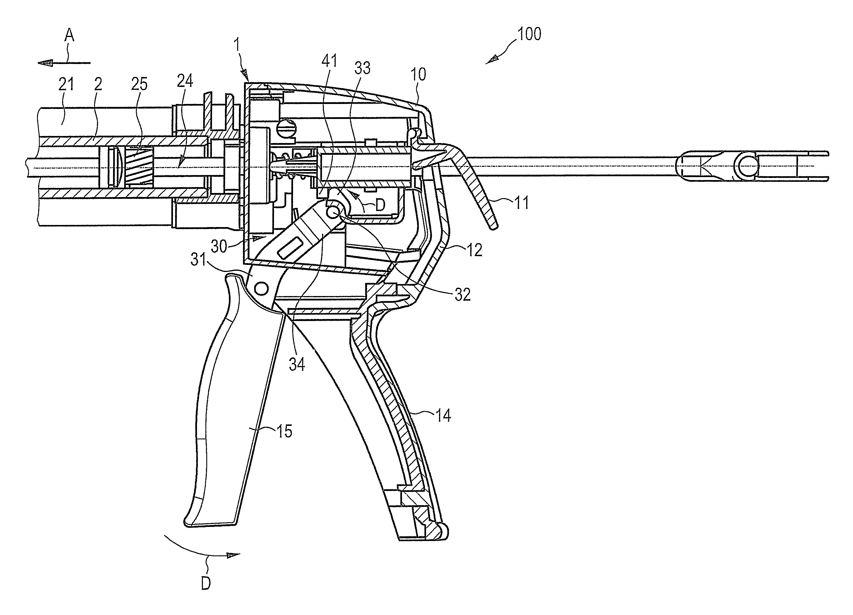
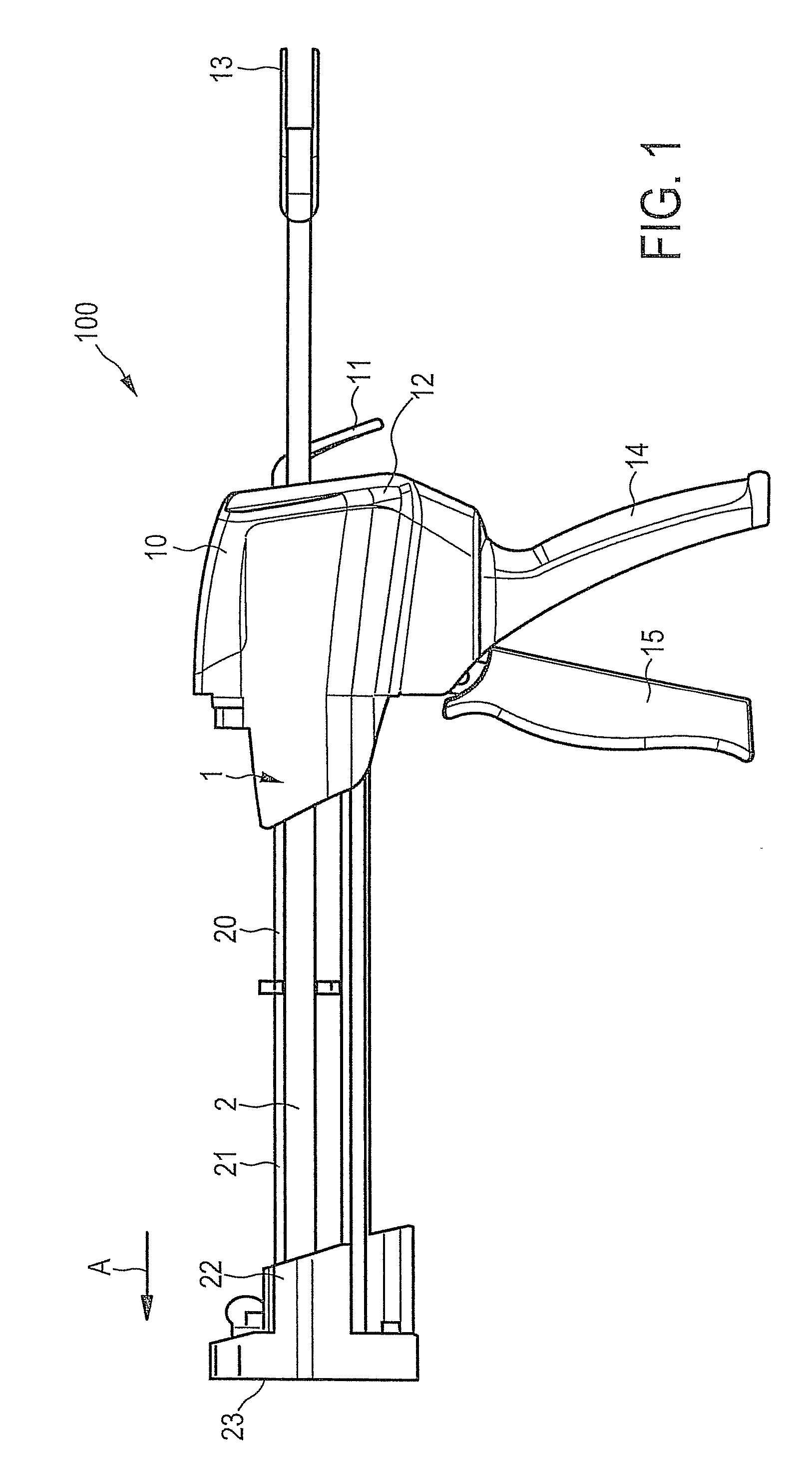
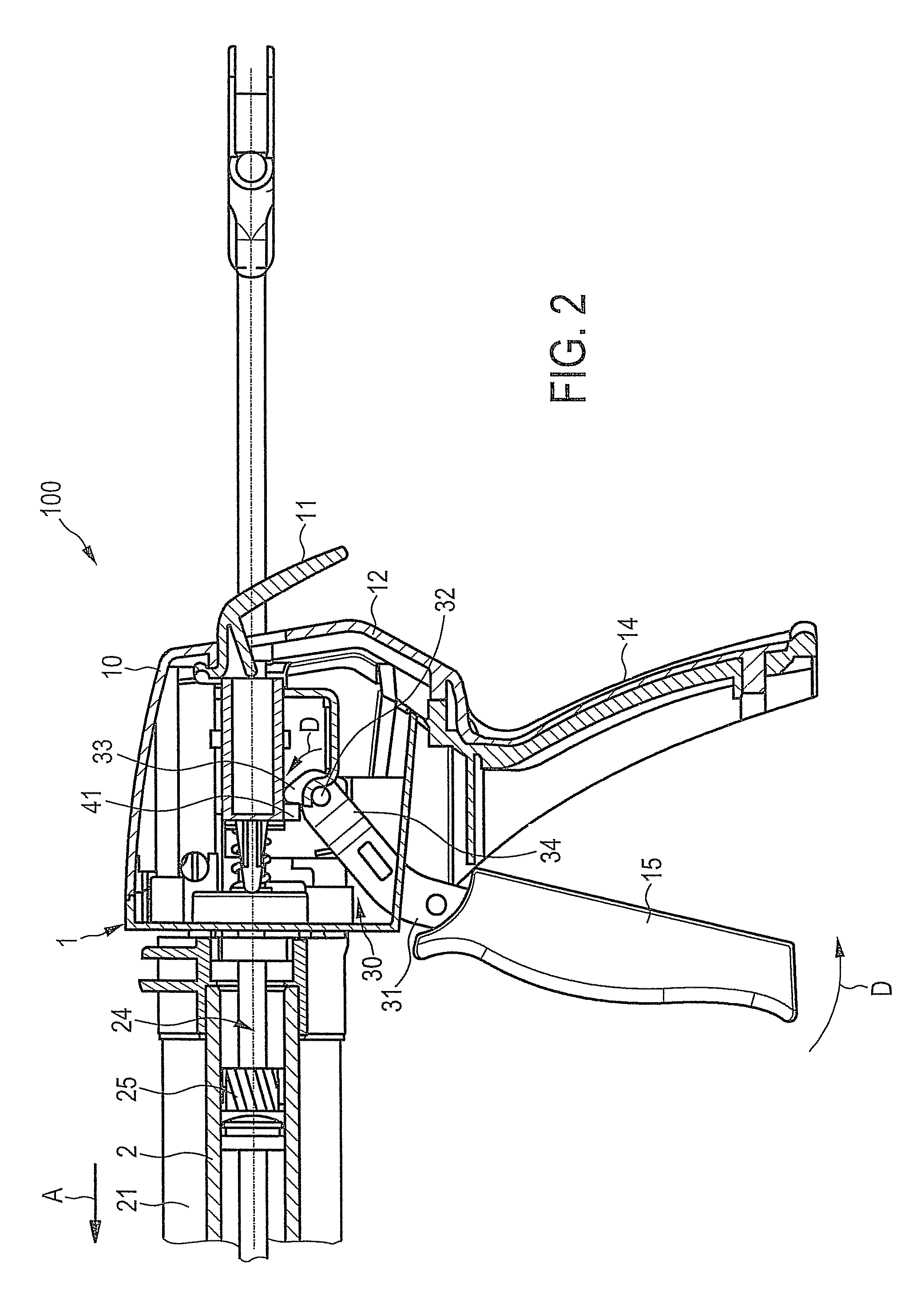
[0042]FIG. 1 shows an extrusion device 100 for the extrusion of single component and, in the present case, particularly multi-component materials for the purposes of filling, gluing, sealing, or the like in construction applications. Such materials and / or other materials are filled in two containers 2, which are designed as cartridges in the present example.

[0043]The containers 2 are arranged in a suitable container receptacle 21 of a housing 1 of the extrusion device 100. The housing 1 extends in the present case substantially along an axial direction A, and has a functional section 20 and a manual operation section 10. The functional section 20 has, substantially, the container receptacle 21 and a processing head 22 which is located on a distal end 23 of the functional section 20 on the processing side. An extrusion opening of each container 2 projects into said processing head 22, and is not portrayed in detail. Materials discharged from the containers 2 are therefore optionally ...


PUM


Abstract

An extrusion device for the extrusion of single- or multi-component materials from at least one container is provided. The extrusion device includes a housing having a functional section and a manual operation section. The housing extends substantially along an axial direction. The functional section includes at least one container receptacle. The manual operation section includes a lever arrangement via which an extrusion rod arrangement can be actuated to extrude materials from the at least one container. The lever arrangement includes a lever body mounted on a rotary axis. The lever body includes a lever push arm on one side of the rotary axis and a lever grip arm on the other side of the rotary axis. The lever push arm acts in a force-transmitting manner on a drive body attached on the extrusion rod arrangement upon actuation of the lever grip arm. The lever body includes a fork which forms at least two fork sections, and a fork trunk, wherein each of the at least two fork sections each extends into a lever push arm, and the fork trunk extends into the lever grip arm.

Description

RELATED APPLICATIONS[0001]The present application claims priority to German Patent Application DE 10 2010 030 841.2, filed Jul. 2, 2010, and entitled “Auspressvorrichtung” (“Extrusion Device”), the entire content of which is incorporated herein by reference.FEDERALLY SPONSORED RESEARCH OR DEVELOPMENT[0002][Not Applicable]MICROFICHE / COPYRIGHT REFERENCE[0003][Not Applicable]BACKGROUND OF THE INVENTION[0004]In sealing or gluing applications, single component or multiple component materials are used, wherein the same are placed in containers, such as plastic sacks, cartridges, or similar packaging. An extrusion device serves to receive such a container and to extrude a single component or multiple component material out of the container for the purpose described above.[0005]An extrusion device of the type indicated above is disclosed in DE 195 33 223 A1, for example. A lever body, which is termed a transport lever in the named prior art, is mounted on a rotary axis, and has a lever push...

Claims


Application Information

Patent Timeline
Patent Type & Authority Patents(United States)
IPC IPC(8): G01F11/00B67D7/70
CPCB05C17/00553B05C17/00596B05C17/0123
Inventor STROBEL-SCHMIDT, RAINERHEFELE, CHRISTIANLEDERLE, HANS-PETER
Owner HILTI AG
Why Eureka
Try Eureka