

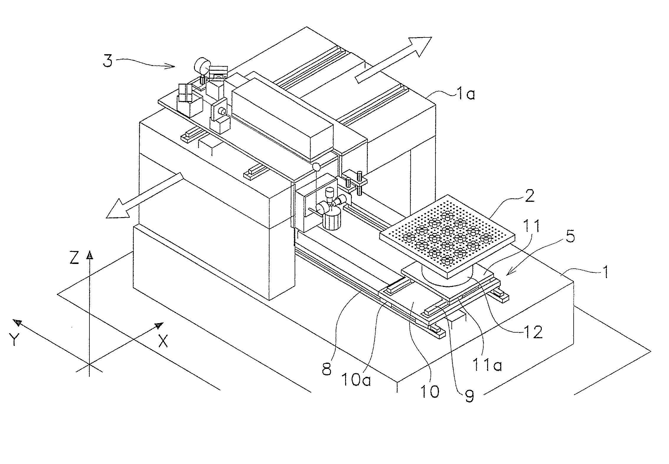
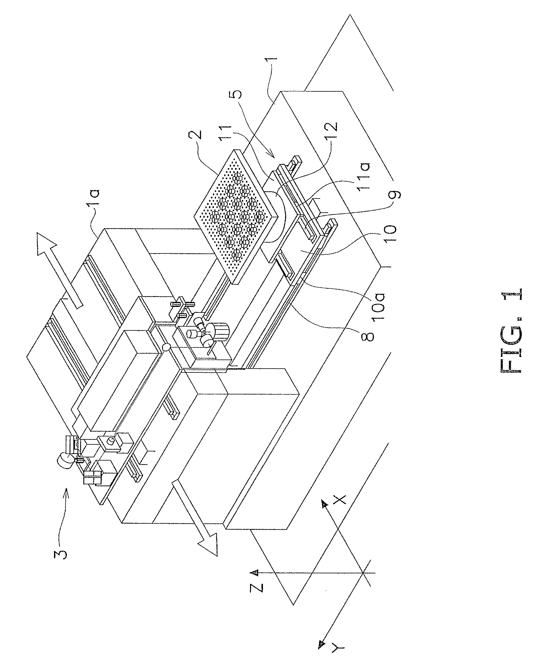
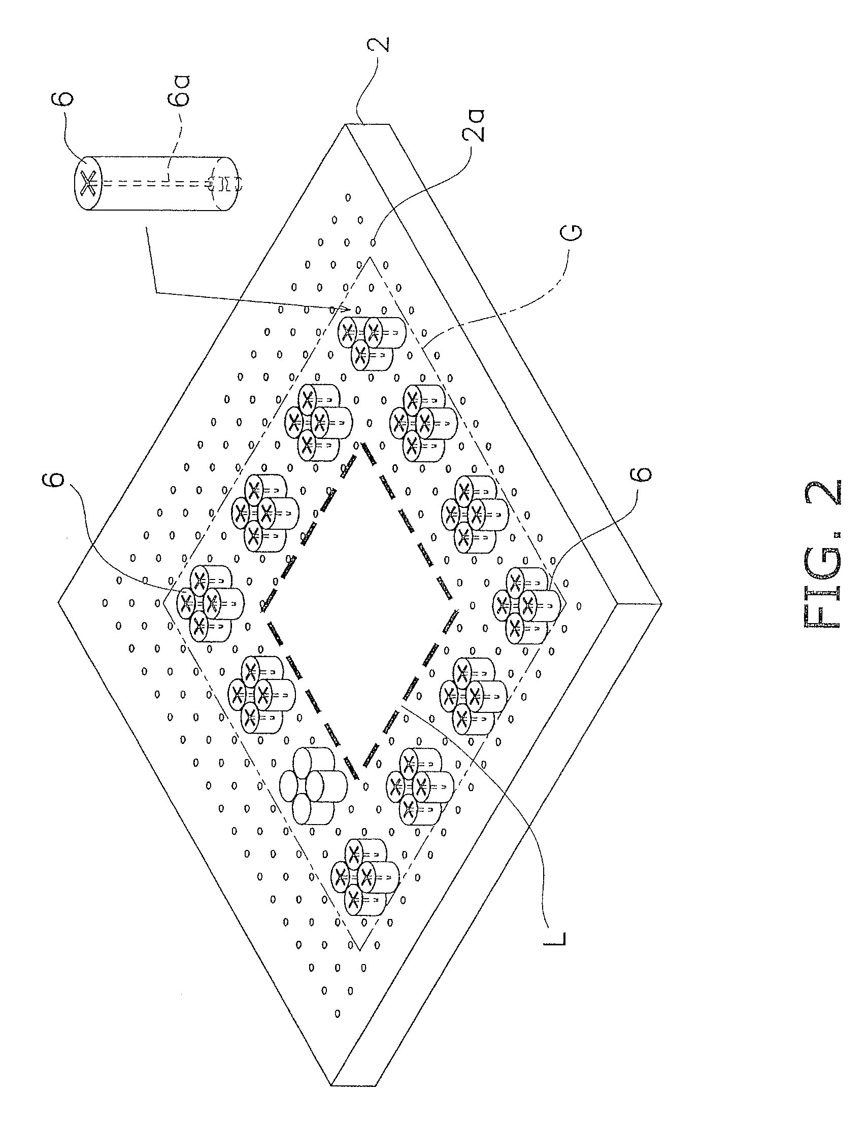
Glass substrate processing device using laser beam
a technology of laser beam and glass substrate, which is applied in glass tempering apparatus, glass making apparatus, manufacturing tools, etc., can solve the problems of long processing time, evaporation of glass substrate, burnt support portions of work tables, etc., and achieve the effect of low cos
- Summary
- Abstract
- Description
- Claims
- Application Information
AI Technical Summary
Benefits of technology
Problems solved by technology
Method used
Image

Examples
first exemplary embodiment
Modifications of First Exemplary Embodiment
[0085](a) In the aforementioned exemplary embodiment, the z-coordinate directional moving mechanism 22 is used as a mechanism for moving the beam focus spots in the z-coordinate direction. Further, the z-coordinate directional moving mechanism 22 is configured to move the hollow motor 17, the x-directional galvano mirror 18, the y-directional galvano mirror 19, and the fθ lens 20 in the z-coordinate direction. However, the work table 2 may be configured to be moved in the z-coordinate direction without moving the hollow motor 17, the x-directional galvano mirror 18, the y-directional galvano mirror 19, and the fθ lens 20.
[0086](b) In the aforementioned exemplary embodiment, the fθ lens is used as a collective lens. However, the collective lens is not limited to the fθ lens as long as it can focus a laser beam.
Alternate Embodiments
[0087]Alternate embodiments will now be explained. In view of the similarity between the first and alternate emb...
second exemplary embodiment
Modification of Second Exemplary Embodiment
[0108]In the second exemplary embodiment, the z-coordinate moving device 22 is used as a mechanism of moving a beam focus spot in the z-coordinate direction. Specifically, the z-coordinate moving device 22 is configured to move the second hollow motor 118 including the collective lens 135. However, the work table 2 may be configured to be moved in the z-coordinate direction without moving the second hollow motor 118 including the collective lens 135.
Other Exemplary Embodiments
[0109]The present invention is not limited to the aforementioned exemplary embodiments. Various changes or modifications can be made for the aforementioned exemplary embodiments without departing from the scope of the present invention.
[0110](a) In the aforementioned exemplary embodiments, components including the diffractive optical element are configured to form four beam focus spots on the circumference of an imaginary circle at an interval of an equal angle, as ill...
PUM
| Property | Measurement | Unit |
|---|---|---|
| wavelength | aaaaa | aaaaa |
| circumference | aaaaa | aaaaa |
| angle | aaaaa | aaaaa |
Abstract
Description
Claims
Application Information