
Hybrid drive speed change device

a technology of hybrid drive and speed change device, which is applied in the direction of transportation and packaging, propulsion by capacitors, and gearing, etc., to achieve the effect of simplifying the assembly work of sensor stator

Inactive Publication Date: 2013-05-28
AISIN AW CO LTD
View PDF20 Cites 25 Cited by
  • Summary
  • Abstract
  • Description
  • Claims
  • Application Information

AI Technical Summary

Benefits of technology

The patent text describes a hybrid drive speed change device for vehicles. The device has a compact design, with a rotation sensor placed appropriately to reduce its axial size. The inner surface of a cylindrical portion in the device is connected to the outer surface of another member via a seal member. This allows the sensor statutory to be fixed to a partition wall with the outer surface of the cylindrical portion. This positioning makes it easy to assemble the sensor stator and simplifies the overall assembly process.

Problems solved by technology

However, JP-A-2004-1708 mentioned above does not describe the installation position of a resolver (rotation sensor) from the viewpoint of reducing the axial dimension of the hybrid drive speed change device, and there has not been revealed how the rotation sensor should be arranged from the viewpoint of reducing the axial dimension of the device.

Method used


Image

  • Hybrid drive speed change device
  • Hybrid drive speed change device
  • Hybrid drive speed change device

Examples


Embodiment Construction

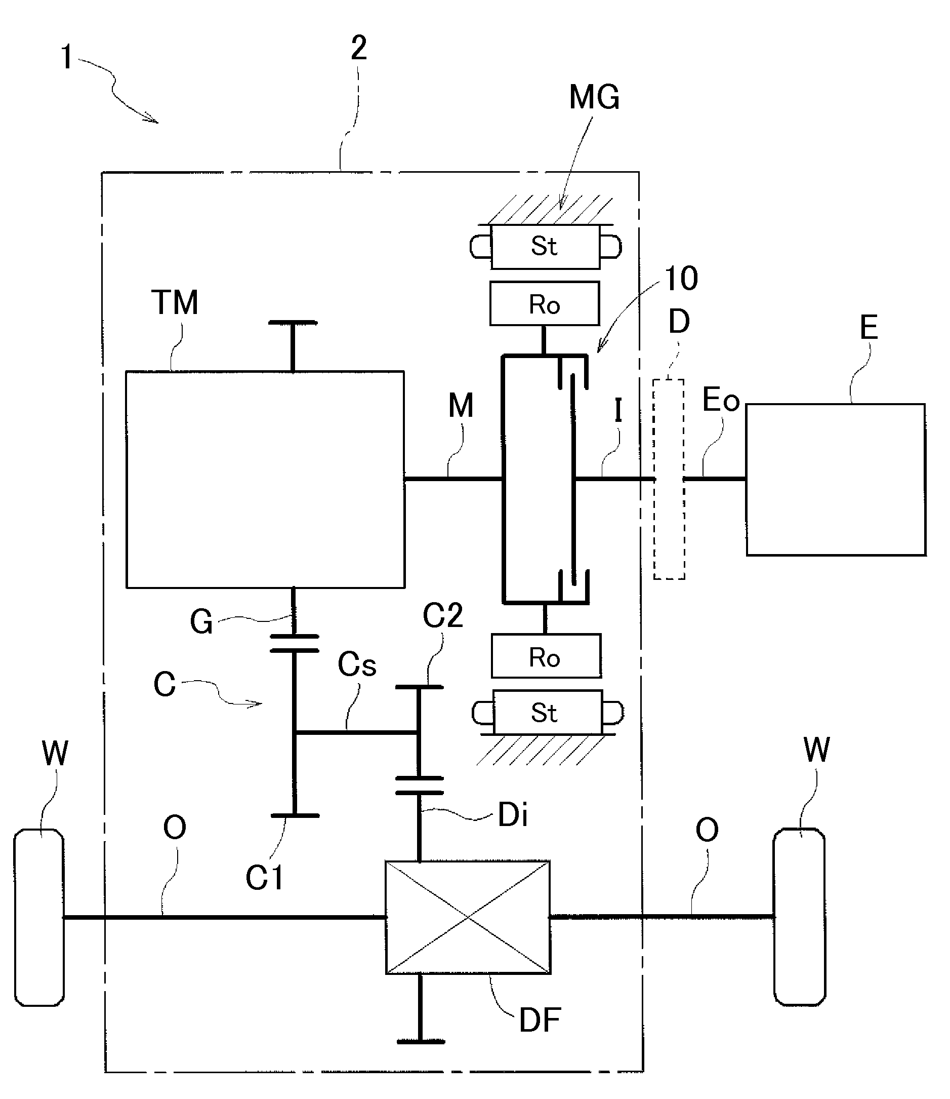
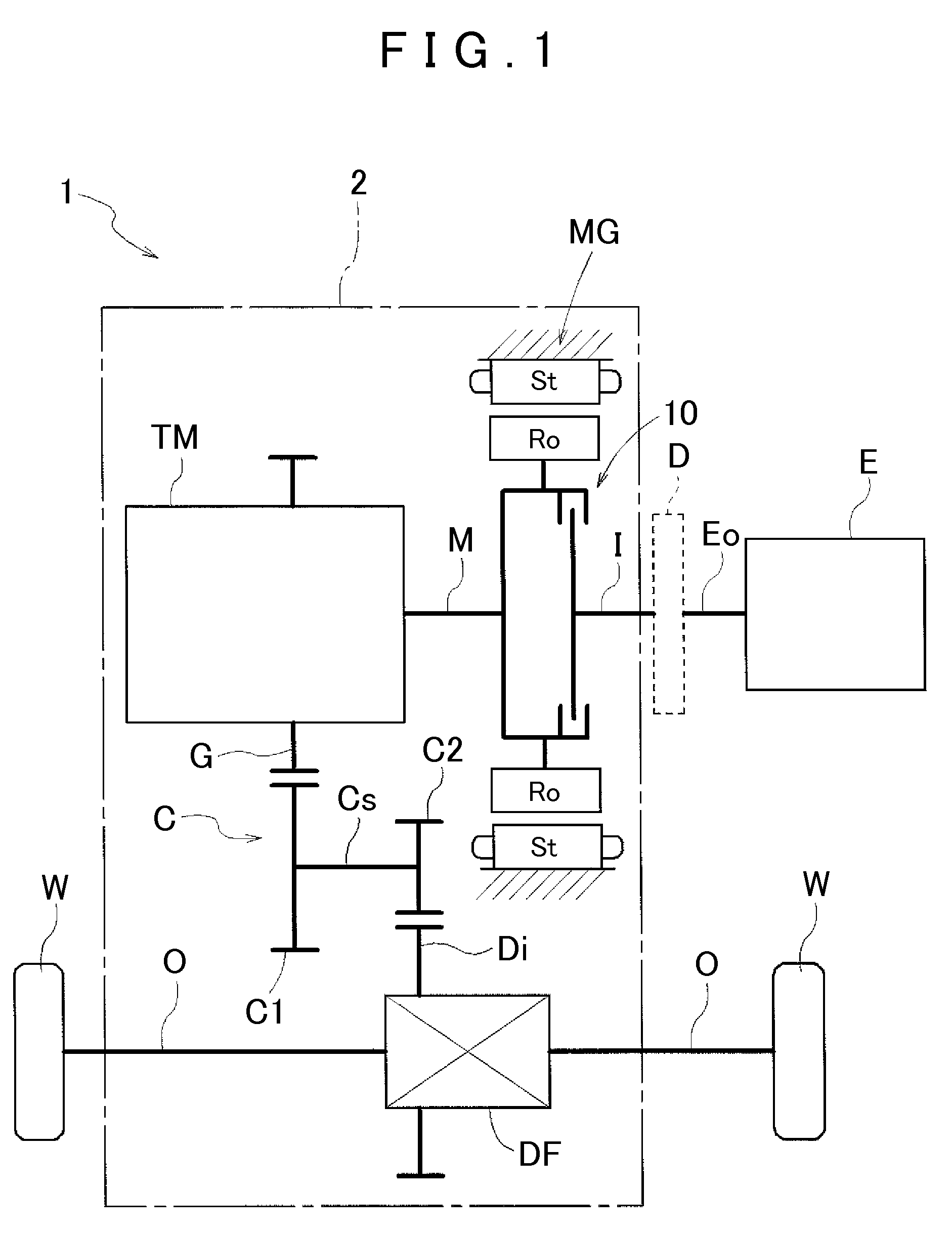
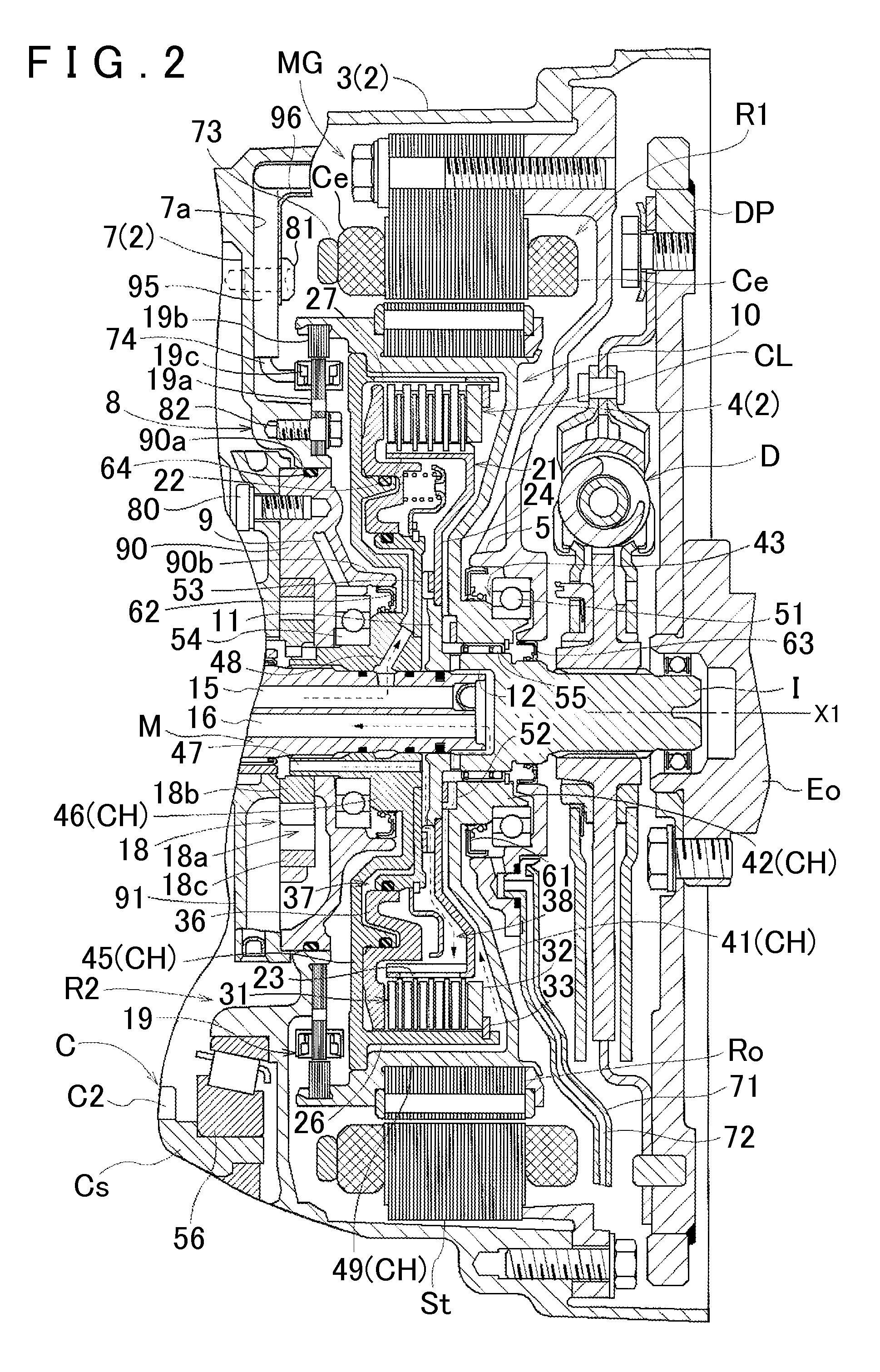
[0028]A hybrid drive speed change device according to an embodiment of the present invention will be described with reference to the drawings. A hybrid drive speed change device 1 is a drive speed change device for a hybrid vehicle that uses one or both of an internal combustion engine E and a rotary electric machine MG as a drive force source for the vehicle. As shown in FIG. 1, the hybrid drive speed change device 1 includes a starting clutch 10 that selectively drivably couples the internal combustion engine E and the rotary electric machine MG to each other, and is formed as a so-called one-motor parallel type hybrid drive speed change device. As shown in FIG. 2, the hybrid drive speed change device 1 includes a resolver 19 that detects the rotational angle of a rotor Ro of the rotary electric machine MG, and an oil pump 18. The thus configured hybrid drive speed change device 1 according to the embodiment is characterized in that the resolver 19 is disposed radially outwardly o...


PUM


Abstract

To provide a hybrid drive speed change device in which a rotation sensor can be disposed appropriately from the viewpoint of reducing the axial dimension of the device. A rotary electric machine MG is disposed coaxially with an input shaft M, and includes a stator St and a rotor Ro provided radially inwardly of the stator St. An oil pump 18 includes a pump case 90, 91 in which a pump chamber 18a is formed, and a pump rotor 18b rotatably housed in the pump chamber 18a. The pump rotor 18b is disposed coaxially with the input shaft M. A rotation sensor 19 is disposed radially outwardly of the pump chamber 18a and radially inwardly of the stator St of the rotary electric machine MG, and disposed to overlap the oil pump 18 as seen from the radial direction of the input shaft M.

Description

INCORPORATION BY REFERENCE[0001]The disclosure of Japanese Patent Application No. 2010-081513 filed on Mar. 31, 2010, and PCT Patent Application No. PCT / JP2011 / 052863 filed on Feb. 10, 2011 including the specification, drawings and abstract is incorporated herein by reference in its entirety.BACKGROUND OF THE INVENTION[0002]The present invention relates to a hybrid drive speed change device including a friction engagement device having an input-side member drivably coupled to an internal combustion engine, an output-side member drivably coupled to a speed change mechanism, and an engagement mechanism that selectively drivably couples the input-side member and the output-side member to each other, the hybrid drive speed change device further including a rotary electric machine having a rotor drivably coupled to the output-side member, a rotation sensor that detects the rotational angle of the rotor, an oil pump, the speed change mechanism, and an input shaft serving as a shaft that d...

Claims


Application Information

Patent Timeline
Patent Type & Authority Patents(United States)
IPC IPC(8): F16H37/06B60K6/48B60L50/16
CPCB60K6/387B60K6/405B60K6/48B60L11/005B60L11/14Y10T74/19051Y02T10/6221Y02T10/7022Y02T10/7077Y02T10/70Y10T74/19014B60L2240/36B60L50/40B60L50/16Y02T10/62Y02T10/7072B60K2006/4825F16D25/123F16D25/0638
Inventor KASUYA, SATORUKATOU, HIROSHIKITOU, MASASHIKATO, TAKAYOSHISEKI, YUICHI
Owner AISIN AW CO LTD
Learn More