
Sutures for use in the repair of defects in the anulus fibrosus

a technology of annular fibers and sutures, which is applied in the field of sutures for use in the repair of annular fiber defects, can solve the problems of reduced treatment effect of disc degeneration, so as to facilitate the healing of the anterior longitudinal ligament and facilitate the anterior longitudinal ligament. , the effect of facilitating the healing of the posterior longitudinal ligamen

Inactive Publication Date: 2013-05-28
ANOVA
View PDF12 Cites 7 Cited by
  • Summary
  • Abstract
  • Description
  • Claims
  • Application Information

AI Technical Summary

Benefits of technology

The invention is a method and device for strengthening the attachment of sutures to bone, particularly in spinal surgery. The invention involves the use of anchors with enlarged diameters or cross-sections that can be attached to the ends of sutures. These anchors can be in the form of a ring or a spool and come with a pointed tip and attachment means. The invention can be used to heal various parts of the spine, contain bone growth material, and restrict spinal motion. Overall, the invention improves the stability and strength of spinal surgery procedures.

Problems solved by technology

The nucleus becomes thinner and less able to handle compression loads.
The redundant annular fibers are less effective in controlling vertebral motion.
Current surgical treatments for disc degeneration are destructive.
The first two groups of procedures compromise the treated disc.
Fusion procedures transmit additional stress to the adjacent discs, which results in premature disc degeneration of the adjacent discs.
These destructive procedures lead to acceleration of disc degeneration.
Current nucleus replacements (NRs) may cause lower back pain if too much pressure is applied to the anulus fibrosus.
Compressed nerves cause back and leg or arm pain.
The opening in the anulus fibrosus is enlarged during surgery, further weakening the anulus fibrosus.
Although microlumbar discectomy decreases or eliminates a patient's leg or arm pain, the procedure damages weakened discs.

Method used


Image

  • Sutures for use in the repair of defects in the anulus fibrosus
  • Sutures for use in the repair of defects in the anulus fibrosus
  • Sutures for use in the repair of defects in the anulus fibrosus

Examples


Embodiment Construction

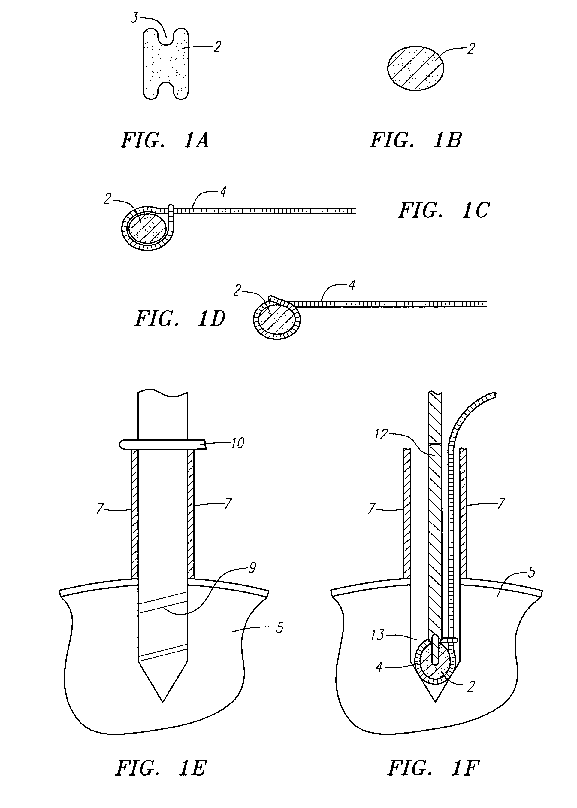
[0063]FIG. 1A is an anterior view of one embodiment of the invention. Device 2 is a spool having indentation 3 adapted for placement of a suture around the spool such that the suture fits at least partially within the indentation. Indentation 3 aids in keeping the suture looped around spool 2. Device 2 may be made of metal such as Titanium, plastic such as polyethylene or PEEK, bioresorbable materials, or cured cement such as PMMA. Suitable bio-resorbable materials include polylactic acid (PLA), polyglycolic acid (PGA), poly (ortho esters), poly(glycolide-co-trimethylene carbonate), poly-L-lactide-co-6-caprolactone, polyanhydrides, poly-n-dioxanone, and poly(PHB-hydroxyvaleric acid), FIG. 1B is a lateral view of spool 2. FIG. 1C is a lateral view of spool 2 and suture 4 looped around spool 2. FIG. 1D is a lateral view of the embodiment of the invention drawn in FIG. 1C. Suture 4 has been tightened around spool 2.

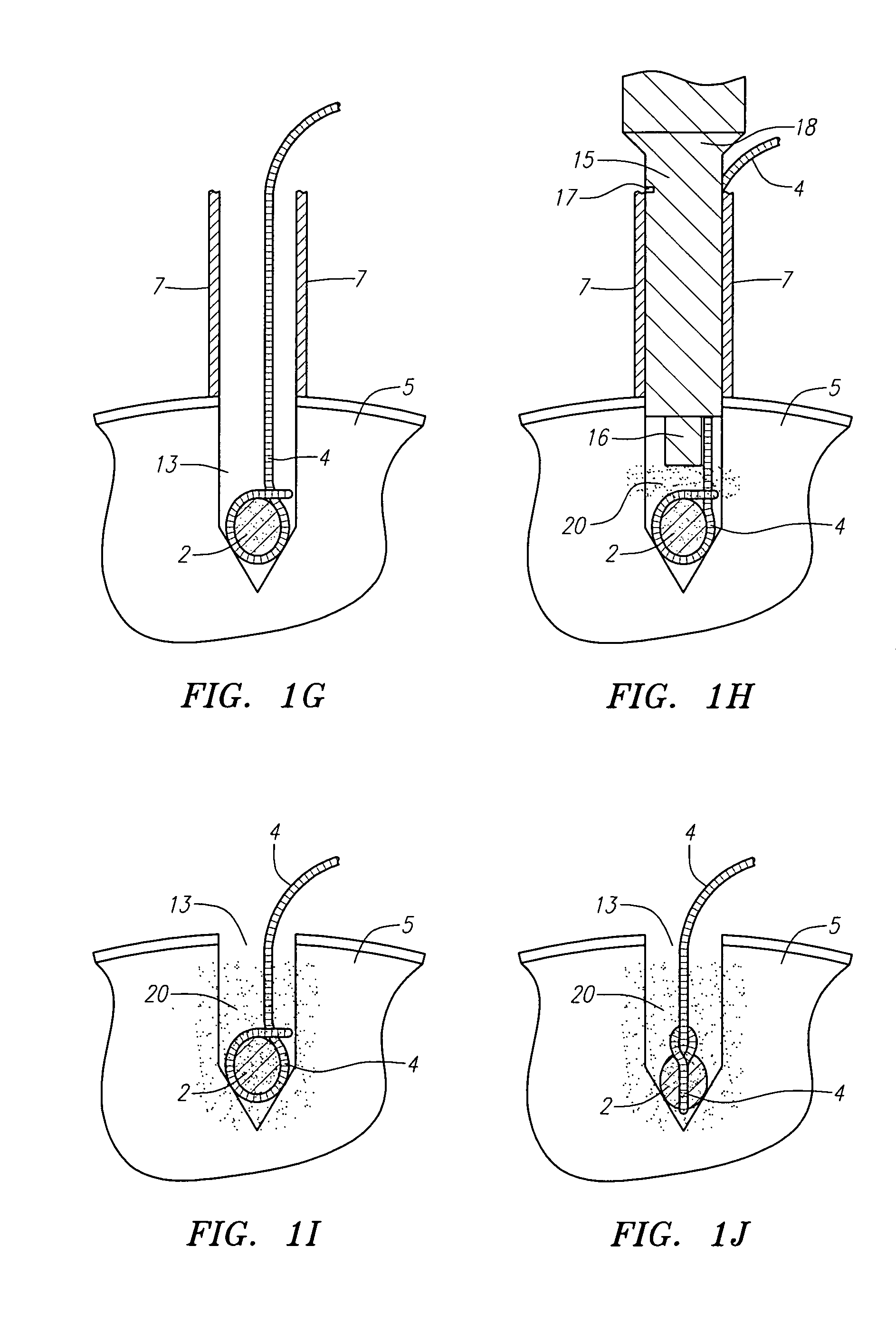
[0064]FIG. 1E is a sagittal cross section of a portion of bone 5, drill...


PUM

PropertyMeasurementUnit
water contentaaaaaaaaaa

Abstract

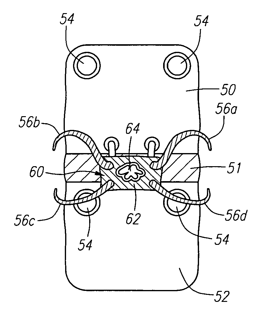
Methods and devices for fixing a defect in a vertebral disc of a patient. One method includes providing first, second, third, and fourth sutures. The first and second sutures are fastened to a vertebra cranial to the vertebral disc at first and second locations, respectively. The third and fourth sutures are fastened to a vertebra caudal to the vertebral disc at third and fourth locations, respectively. A device, such as a mesh device, is positioned adjacent the defect. The first, second, third, and fourth sutures are then positioned against the device, on the side of the device opposite of the defect. Tension is then applied to the first, second, third, and fourth sutures. Each of the first, second, third, and fourth sutures are then attached to at least one of the first, second, third, and fourth sutures, thereby holding the device adjacent the defect.

Description

RELATED APPLICATIONS[0001]This application claims the benefit of U.S. Provisional Patent Application 60 / 748,518, filed Dec. 8, 2005, the entirety of which is hereby expressly incorporated by reference herein in its entirety.BACKGROUND OF THE INVENTION[0002]The human intervertebral disc is an oval to kidney bean-shaped structure of variable size depending on the location in the spine. The outer portion of the disc is known as the anulus fibrosus (AF). The anulus fibrosus is formed of approximately 10 to 60 fibrous bands or layers. The fibers in the bands alternate their direction of orientation by about 30 degrees between each band. The orientation serves to control vertebral motion (one half of the bands tighten to check motion when the vertebra above or below the disc are turned in either direction).[0003]The anulus fibrosus contains the nucleus pulposus (NP). The nucleus pulposus serves to transmit and dampen axial loads. A high water content (approximately 70-80%) assists the nuc...

Claims


Application Information

Patent Timeline
Patent Type & Authority Patents(United States)
IPC IPC(8): A61F2/44
CPCA61B17/0401A61B17/8811A61F2/442A61B2017/0414A61B2017/044A61B2017/0458A61B2019/306A61F2002/30062A61F2002/30451A61F2002/30932A61F2002/4435A61F2002/4495A61F2002/4631A61F2210/0004A61F2220/0058A61B2090/036
Inventor FERREE, BRET A.
Owner ANOVA
Learn More