
Duty cycle correction circuit

a duty cycle and circuit technology, applied in pulse manipulation, pulse duration/width modulation, pulse technique, etc., can solve problems such as significant current consumption, and achieve the effects of reducing circuit area and current consumption, simplifying internal structure, and fast circuit operation ra

Active Publication Date: 2013-05-28
SK HYNIX INC
View PDF10 Cites 2 Cited by
  • Summary
  • Abstract
  • Description
  • Claims
  • Application Information

AI Technical Summary

Benefits of technology

The present invention is a duty cycle correction circuit that has a simple internal structure and operates quickly. It aims to minimize circuit area and current consumption by simplifying the internal structure. This means that the circuit can perform its duties more efficiently and with less complexity.

Problems solved by technology

Meanwhile, a duty cycle correction circuit generally occupies a relatively large circuit area and has a complicated structure, thereby consuming significant current.

Method used


Image

  • Duty cycle correction circuit
  • Duty cycle correction circuit
  • Duty cycle correction circuit

Examples


Embodiment Construction

[0020]Exemplary embodiments of the present invention will be described below in more detail with reference to the accompanying drawings. The present invention may, however, be embodied in different forms and should not be construed as limited to the embodiments set forth herein. Rather, these embodiments are provided so that this disclosure will be thorough and complete, and will fully convey the scope of the present invention to those skilled in the art. Throughout the disclosure, like reference numerals refer to like parts throughout the various figures and embodiments of the present invention.

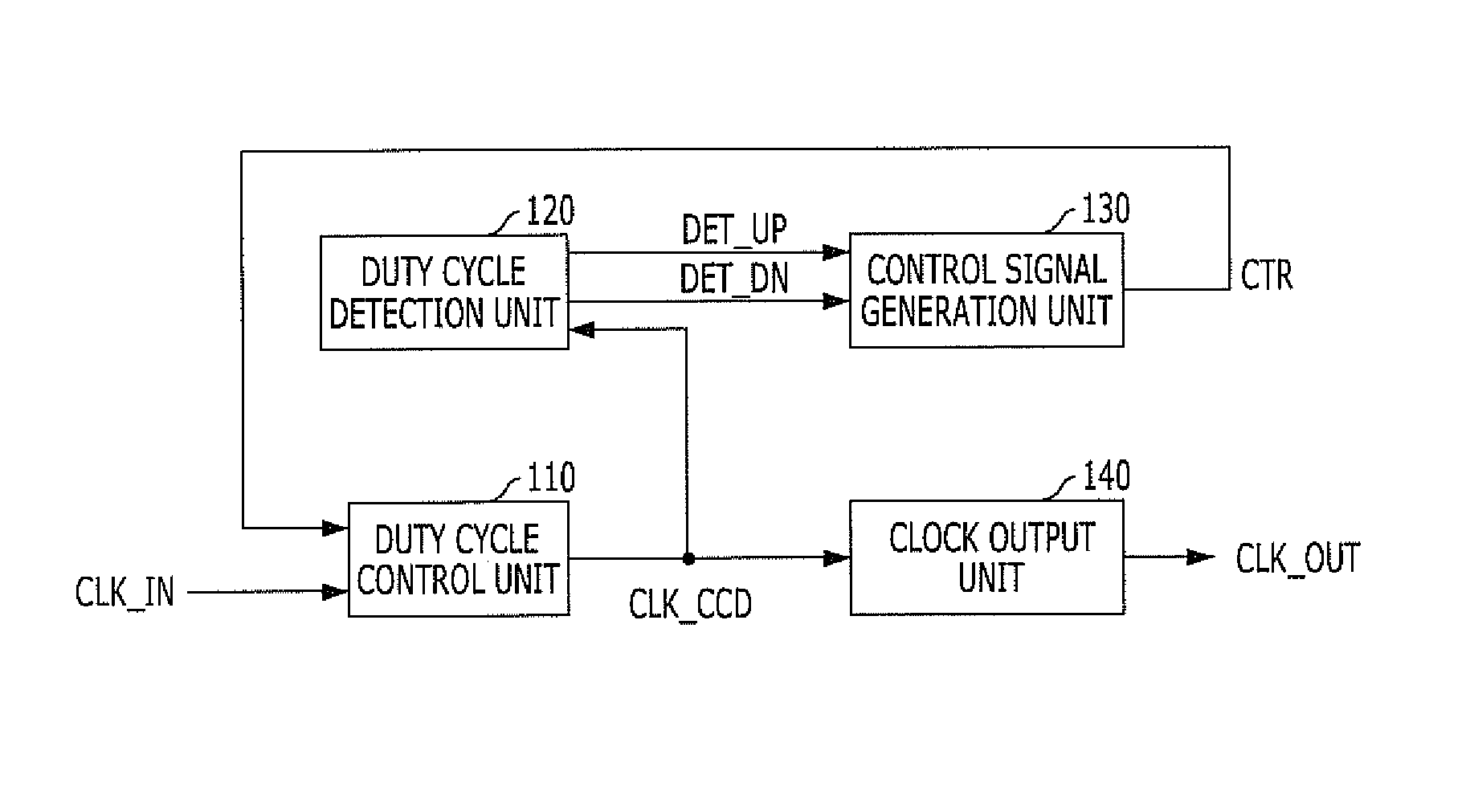
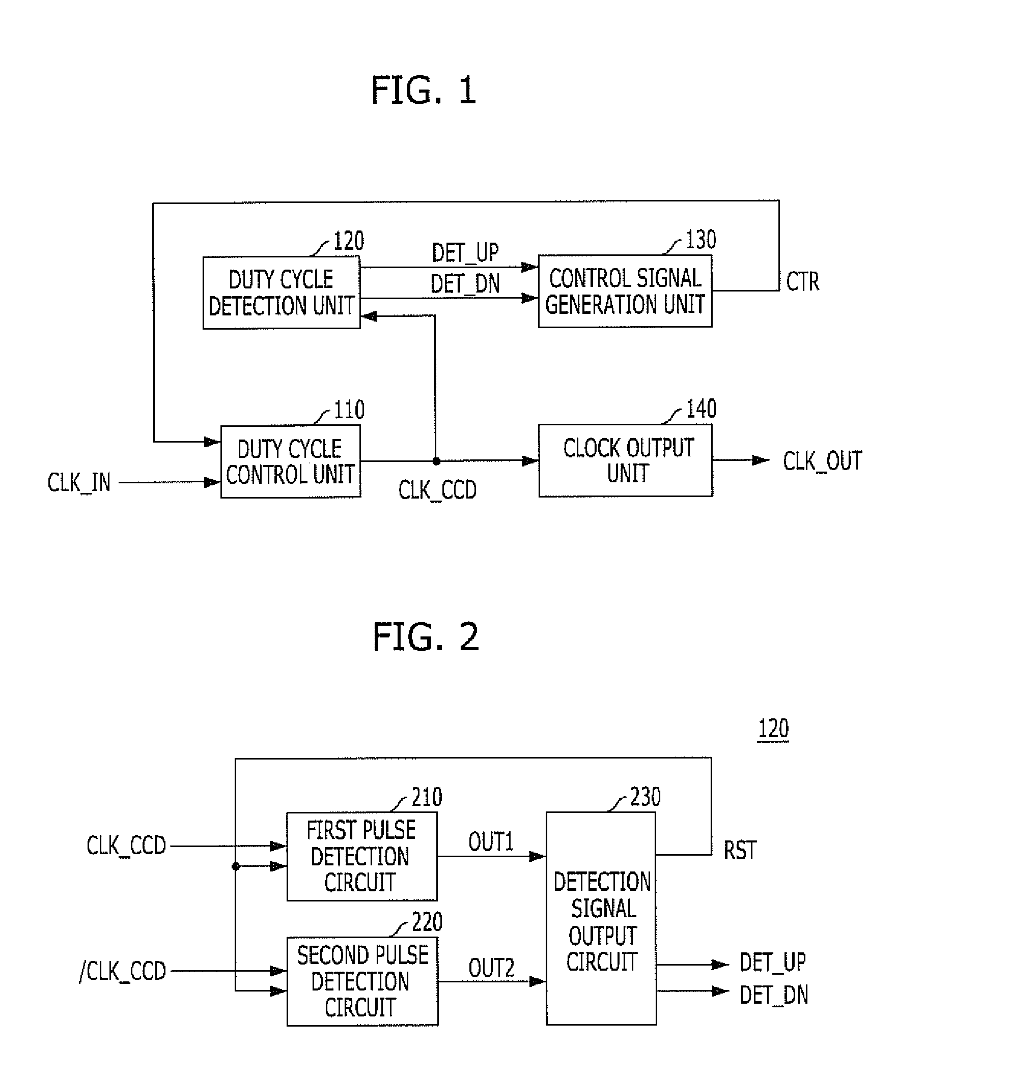
[0021]FIG. 1 is a block view illustrating a duty cycle correction circuit in accordance with an embodiment of the present invention.

[0022]Referring to FIG. 1, the duty cycle correction circuit includes a duty cycle control unit 110, a duty cycle detection unit 120, a control signal generation unit 130, and a clock output unit 140.

[0023]The duty cycle control unit 110 receives a fed-back cont...


PUM


Abstract

A duty cycle correction circuit includes a duty cycle control unit configured to generate a corrected clock signal by correcting a duty cycle of an input clock signal in response to a control signal, a duty cycle detection unit configured to detect a duty cycle of the corrected clock signal and output a detection signal, and a control signal generation unit configured to generate the control signal in response to the detection signal.

Description

CROSS-REFERENCE TO RELATED APPLICATIONS[0001]The present application claims priority of Korean Patent Application No. 10-2010-0129894, filed on Dec. 17, 2010, which is incorporated herein by reference in its entirety.BACKGROUND OF THE INVENTION[0002]Exemplary embodiments of the present invention relate to a technology for designing a semiconductor integrated circuit, and more particularly, to a duty cycle correction circuit (DCC) which corrects a duty cycle of a clock signal and outputs a clock signal with a corrected duty cycle.[0003]In general, a semiconductor device including a Double Data Rate Synchronous Dynamic Random Access Memory (DDR SDRAM) includes diverse internal circuits for diverse operations, and among the internal circuits is a duty cycle correction circuit (DCC) which receives a clock signal and corrects the duty cycle of the clock signal to be a desired duty cycle. The duty cycle correction circuit may receive an internal clock signal outputted from a Delay Locked ...

Claims


Application Information

Patent Timeline
Patent Type & Authority Patents(United States)
IPC IPC(8): H03K3/017
CPCH03K5/1565
Inventor AHN, SEUNG-JOONLEE, JONG-CHERN
Owner SK HYNIX INC
Learn More