Exposure method and exposure apparatus

a technology of exposure apparatus and exposure method, which is applied in the direction of photomechanical apparatus, instruments, printing, etc., can solve the problems of affecting the efficiency of the exposure process, and consuming more time in the process, so as to achieve the effect of enhancing productivity and facilitating the exposure process

Active Publication Date: 2013-05-28
V TECH CO LTD
View PDF34 Cites 10 Cited by
  • Summary
  • Abstract
  • Description
  • Claims
  • Application Information

AI Technical Summary

Benefits of technology

[0011]The present invention was achieved in view of the above circumstances, and has as its object to provide an exposure method and an exposure apparatus that enable efficiently irradiation of a substrate having a wide exposure area by using a small mask.
[0017]According to the exposure method and the exposure apparatus of the present invention, while the substrate transfer portion transfers the substrate, the exposure process can be continuously performed so as to transfer the mask aperture shape. In this manner, even when the small mask is employed, it is not necessary to intermittently repeat the exposure process by the step motion of the substrate. Thereby, the exposure process can be efficiently performed on the substrate having a wide exposure area.
[0018]Moreover, the reference position of the substrate is detected by using the preformed reference pattern on the substrate. The mask position can be adjusted, based on the reference position. In this manner, the exposure process for the predetermined area on the substrate can be precisely performed. Together with this, it is not necessary to form alignment marks on the mask and the substrate in order to adjust the mask position. Thereby, the fabrication thereof becomes easy.
[0019]In one embodiment, there is provided an exposure apparatus that adjusts the mask position along the perpendicular direction to the substrate transfer direction. With respect to this exposure apparatus, the mask position along the perpendicular direction to the substrate transfer direction can certainly be adjusted, based on the reference position along the perpendicular direction to the substrate transfer direction. In this manner, the exposure process for the exposure area can be precisely performed along the substrate transfer direction.
[0020]In one embodiment, there is provided an exposure apparatus that adjusts the mask azimuth to the substrate transfer direction. With respect to this exposure apparatus, the mask azimuth can certainly be adjusted, based on the offset azimuth to the substrate transfer direction. In this manner, the mask position is adjusted further precisely in response to a positional change of the substrate being transferred. Accordingly, the exposure process for the predetermined area can be performed further precisely.
[0021]In one embodiment, there is provided an exposure apparatus that brings the sheet type substrate from the storage roll and reels it around the wind roll. In this manner, the sheet type substrate moves along the perpendicular plane to the optical path in the exposure portion. With respect to this exposure apparatus, it is not necessary to intermittently repeat the exposure process for each exposure area corresponding to the unit substrate by the step motion of the substrate, where the plurality of exposure areas consecutively places on the sheet type substrate. Accordingly, the exposure process can be highly-efficiently performed on the plurality of substrates so as to enable enhanced productivity.

Problems solved by technology

In this manner, since the exposure process takes a long time, there exists a problem that disturbs efficiently carrying out the exposure process.
Thereby, the exposure process takes more time so that the problem becomes further dominant.
In addition, even if a mask having a relative large size is employed in order to decrease the repetition frequency of the exposure process, a large amount of exposure energy is required.
Accordingly, due to limited light source power, the exposure time should be longer.
As a result, there exists a problem that disturbs the decrease in the exposure time.
Accordingly, there exists a problem in that the fabrication process of the substrate (base material) and the mask becomes complicated.

Method used


Image

  • Exposure method and exposure apparatus
  • Exposure method and exposure apparatus
  • Exposure method and exposure apparatus

Examples


Embodiment Construction

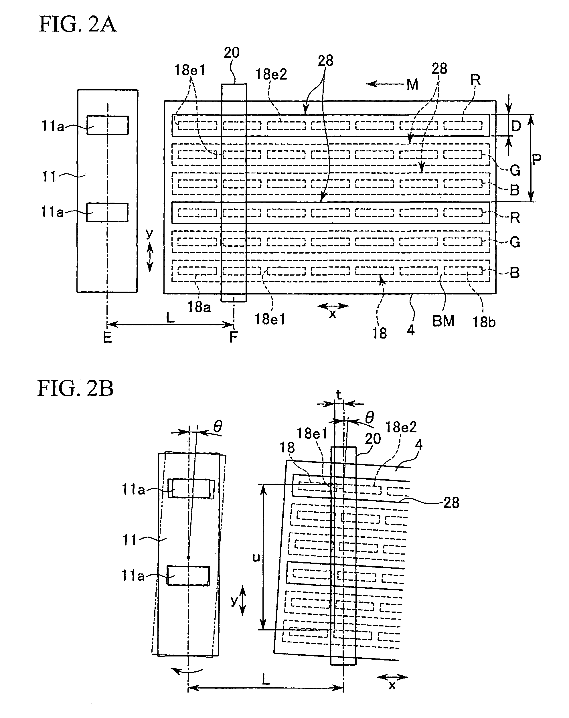
[0057]An exposure apparatus according to a first embodiment of the present invention will be described hereinbelow with reference to FIG. 1, FIG. 2A and FIG. 2B.

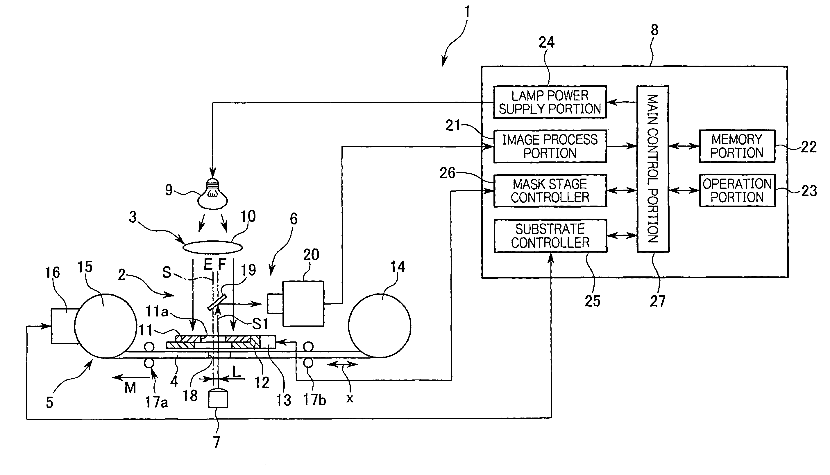
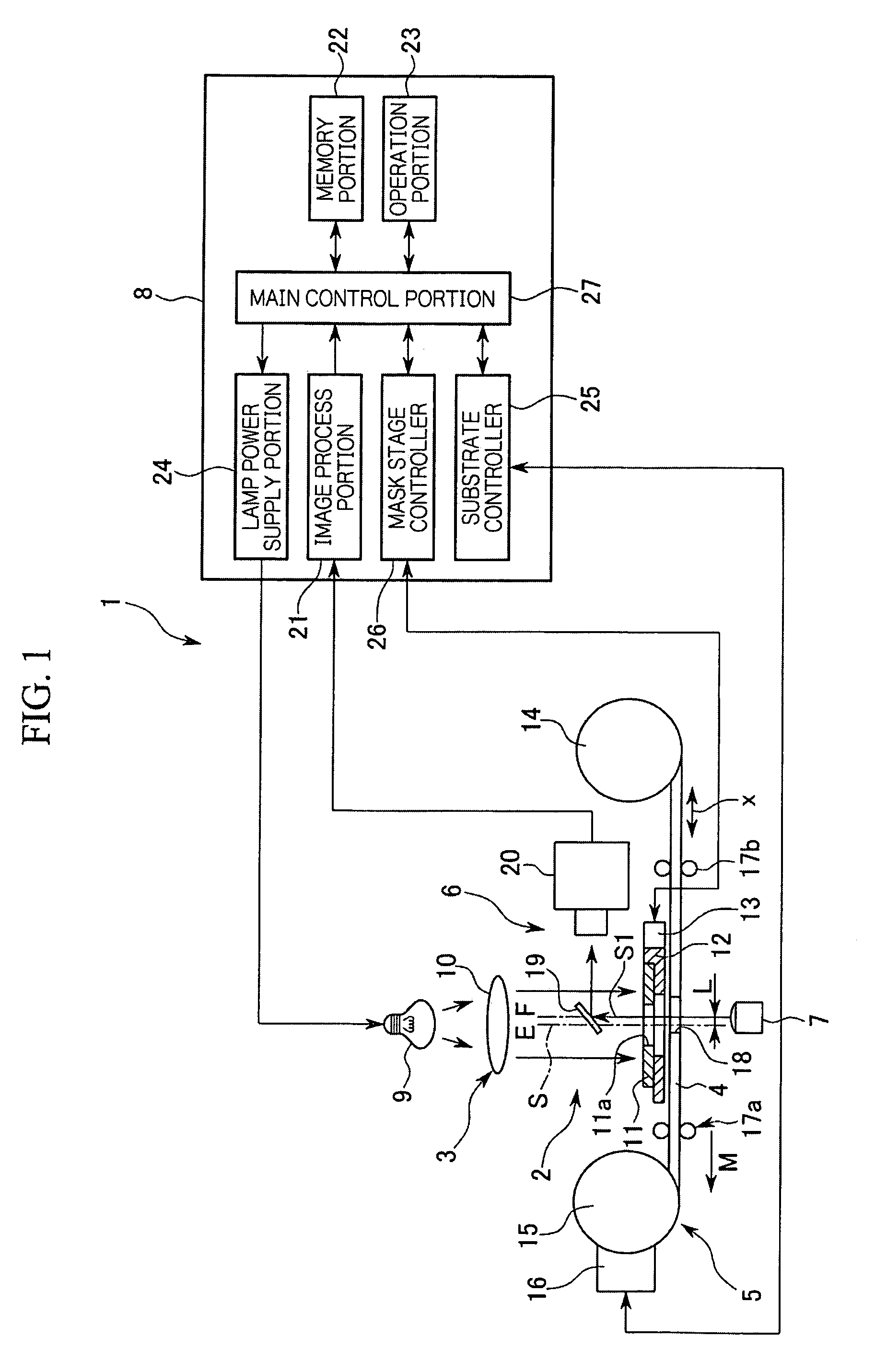
[0058]FIG. 1 shows a schematic diagram of the exposure apparatus according to the first embodiment of the present invention. As shown in FIG. 1, the exposure apparatus 1 includes an exposure optical system 3 which is provided in an exposure station (exposure portion) 2, a substrate transfer portion 5 that transfers a substrate 4 of an exposed object below the exposure optical system 3, a image sensor portion 6 that takes an image of a specific part on the substrate 4, an illumination 7 that illuminates for recognizing the image of the substrate 4 from the under side thereof in the exposure station 2, and a control portion 8 that connects with and controls the above described portions. The exposure light is emitted from the exposure optical system 3 to the substrate 4 passing through an aperture of a mask 11 which is provided...


PUM

PropertyMeasurementUnit
areaaaaaaaaaaa
velocityaaaaaaaaaa
distanceaaaaaaaaaa

Abstract

In an exposure apparatus, exposure light from a lamp (continuous light source) (9) is applied at an exposure station (exposure section) (2) to a substrate (4), which is being transferred at a fixed speed in a fixed direction by a substrate transfer section (5), through a mask (11) arranged on an optical axis (optical path) (S) of an exposure optical system (3). At the time of exposing an image of an opening section (11a) of the mask (11) on the substrate (4), the front edge and the side edge (pattern edge) of a pixel (reference pattern) (18) previously formed on the substrate (4) are photographed by a linear CCD (20) of an imaging section (6), and a reference position in the transfer direction and a direction vertical to such direction on the substrate (4) is detected. When the pixel (18) imaged by the imaging section (6) is shifted to an exposure position (E) form an imaging position (F), the exposure station (2) continuously exposes an exposure region along the transfer direction of the substrate (4) while adjusting the position of the mask (11) so that the position of the mask (11) matches with the reference position on the substrate (4).

Description

TECHNICAL FIELD[0001]The present invention relates to an exposure method and an exposure apparatus for manufacturing a color filter for a liquid crystal panel, and the like.BACKGROUND ART[0002]In manufacturing a color filter for a liquid crystal panel, an exposure method and an exposure apparatus that provide pigmented layers colored red (R), green (G) and blue (B) on a substrate with black matrix patterning are currently known (for example, refer to Patent documents 1 and 2). According to this method, a substrate stage on which a substrate is put is transferred to an exposure portion and located therein. In the exposure portion, exposure light is emitted from a light source portion to a predetermined area on the substrate through a mask smaller than the substrate, during a first exposure process. Subsequently, the substrate stage is moved a predetermined distance by a step motion. After the substrate is moved back into the exposure station (exposure portion), an area which is not e...

Claims


Application Information

Patent Timeline
Patent Type & Authority Patents(United States)
IPC IPC(8): G03B27/32G01B11/00G03F9/00
CPCB29D11/00634G02B5/201G03B27/545G03F7/2002G03F7/70791G03F9/7088G03F9/70G03F9/7084G03F7/0007G03F7/2022G03F7/70733
Inventor IINO, JIN
Owner V TECH CO LTD
Why Eureka
Try Eureka