Dispensing device

a technology of a dispenser and a pore size, which is applied in the direction of packaging foodstuffs, packaging goods, separation processes, etc., can solve the problems of high surface, increased pore size, and inability to compensate for the medium which has been dispensed

Active Publication Date: 2013-06-04
APTAR RADOLFZELL
View PDF36 Cites 12 Cited by
  • Summary
  • Abstract
  • Description
  • Claims
  • Application Information

AI Technical Summary

Benefits of technology

[0011]Even if the liquid filter does not block off the liquid completely, it nevertheless reduces the pressure with which the liquid, after possibly passing through the liquid filter, is forced against the bacteria filter, and there is therefore no risk of the liquid penetrating into the pores of the bacteria filter. It is particularly advantageous for the abovedescribed filter arrangement to be used in dispensing devices which are intended to be changed in position, for example such that the mouth opening of the pressure-equalizing channel is located beneath the liquid level of the medium during use.
[0013]A particularly advantageous configuration is one in which the liquid filter and the bacteria filter each have filter pores, the average size of the filter pores of the liquid filter being greater than the average size of the filter pores of the bacteria filter. Since the pore size significantly influences the surface tension of a liquid which is in contact with the filter and passes into the pores, and therefore the necessary differential pressure between the two sides of the filter for the purpose of detaching the liquid has to increase as the filter pores decrease, it is advantageous to provide larger pores on the liquid filter. If, after the dispensing device has been temporarily upended, a liquid layer remains on the liquid filter, the comparatively large pores mean that it can be detached from the filter even by a fairly low differential pressure between the external surroundings and medium reservoir.
[0014]An average pore diameter for the liquid filter of at least 6 μm has proven to be particularly advantageous. It is particularly advantageous if the liquid filter has an average pore diameter of greater than 10 μm, in particular greater than 15 μm. This comparatively large pore size results in an advantageously low surface tension at the liquid filter, in which case a liquid film on that side of the liquid filter which is directed away from the bacteria filter is reliably removed during pressure equalization and this therefore allows air bubbles then to enter for pressure-equalizing purposes.
[0016]In a development of the invention, the liquid filter and the bacteria filter are spaced apart from one another, preferably by at least 1 mm. This spacing prevents the situation in which medium passing through the liquid filter comes into direct contact with the bacteria filter. Instead, a limited quantity of medium can pass, without having any adverse affect on the bacteria filter, into the region between the liquid filter and bacteria filter, from where this quantity of liquid is forced back into the reservoir during pressure equalization.
[0018]In a development of the invention, the pressure-equalizing channel is designed, at least in certain sections, as a capillary channel. Such a capillary channel hinders medium which has evaporated in the medium reservoir from exiting. A capillary channel here is considered to be a channel of at least 10 mm in length with an average cross-sectional surface area of smaller than 1 mm2, preferably smaller than 0.5 mm2. The provision of a capillary channel means that the pressure-equalizing channel does not have to be sealed in relation to the medium reservoir by a comparatively complex valve. This is advantageous, in particular, since such a valve is difficult to configure in respect of functioning pressure equalization.

Problems solved by technology

This situation is very disadvantageous since the small pore size of the bacteria filter results in a high surface tension of the medium in these pores, which, even after the dispensing device has been transferred back into its rest position, results in this medium remaining on the bacteria filter.
Due to the abovementioned surface tension, this medium then prevents air from entering into the medium reservoir, in which case it is no longer possible to compensate sufficiently for the medium which has been dispensed.
An increase in pore size, however, is problematic since this would help bacteria to penetrate into the bacteria filter again.

Method used


Image

  • Dispensing device
  • Dispensing device
  • Dispensing device

Examples


first embodiment

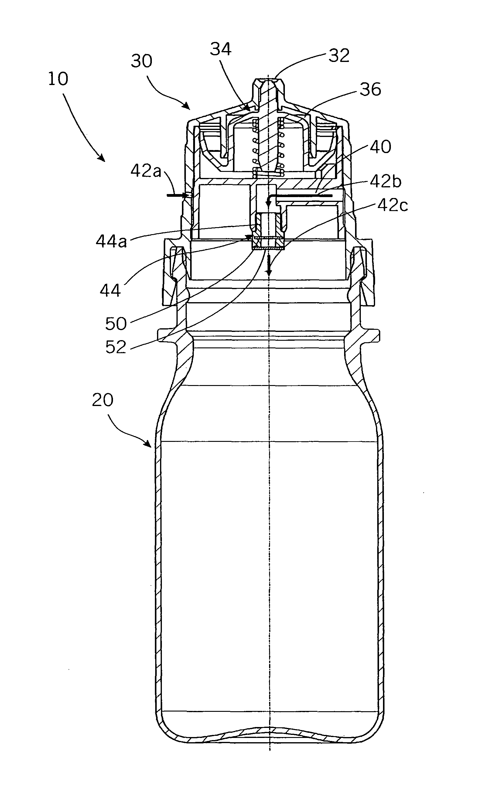
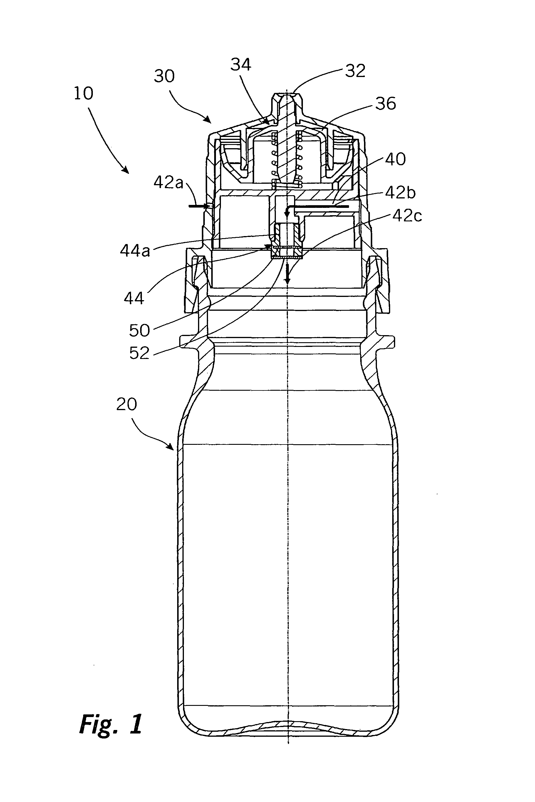
[0020]FIG. 1 shows a sectional side view of a dispensing device according to the invention, and

second embodiment

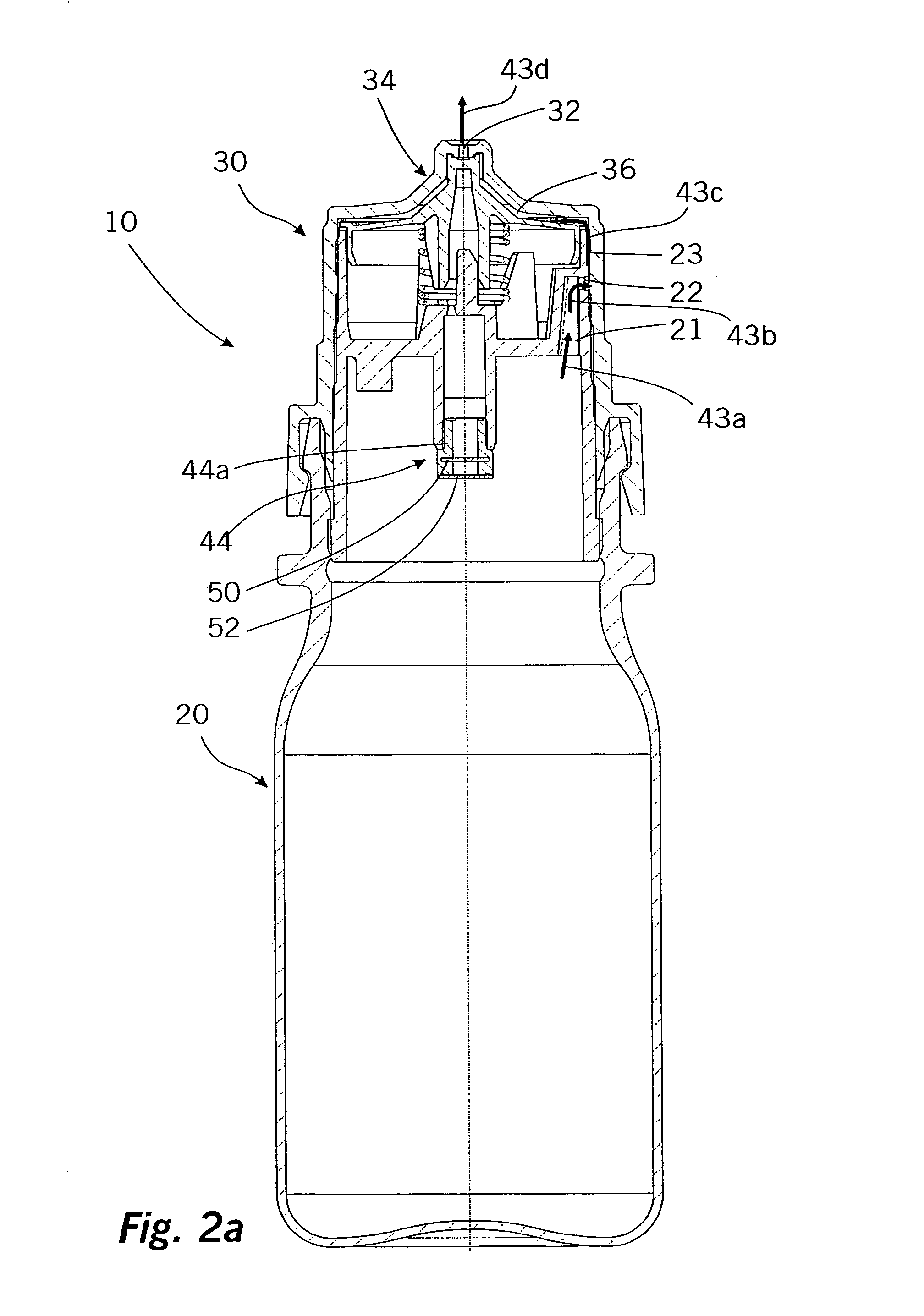
[0021]FIGS. 2a and 2b show two sectional side views of a dispensing device according to the invention.

[0022]FIG. 1 illustrates a dispensing device 10 which has a bottle-like medium reservoir 20 and a metering head 30 latched thereon.

[0023]The metering head 30 contains an outlet opening 32 which is closed by a valve 34 until the pressure in the medium in a valve chamber 36 connected to the medium reservoir has reached a predetermined level. As soon as this is the case, the valve 34 is pushed open by the liquid pressure, counter to a spring force, and the dispensing operation begins. In the case of the dispensing device 10 illustrated, provision is made for this device to be held, during the dispensing operation, such that the outlet opening 32 is oriented downward.

[0024]In the case of the dispensing device illustrated, the medium in the medium reservoir 20 is subjected to pressure by the medium reservoir 20 being compressed manually. The medium reservoir 20 is connected to the valve ...


PUM

PropertyMeasurementUnit
pore sizeaaaaaaaaaa
pore sizeaaaaaaaaaa
lengthaaaaaaaaaa

Abstract

The invention relates to a dispensing device for a liquid medium, having a medium reservoir for accommodating the medium, having a dispensing opening for dispensing the medium from the medium reservoir, and having a pressure-equalizing channel which opens out into the medium reservoir and has a microbiologically active filter arrangement inserted therein.According to the invention, the filter arrangement has a liquid filter oriented in the direction of the medium reservoir and a bacteria filter oriented away from the medium reservoir.

Description

APPLICATION AREA AND PRIOR ART[0001]The invention relates to a dispensing device for a liquid medium, having a medium reservoir for accommodating the medium, a dispensing opening for dispensing the medium from the medium reservoir, and a pressure-equalizing channel which opens out into the medium reservoir and has a microbiologically active filter arrangement inserted therein.[0002]Dispensing devices of the type in question are known from the prior art. They are used for pharmaceutical liquids, for example for eye drops and nose drops. In the case of the dispensing devices of the type in question, the dispensing operation leads to the quantity of medium located in the medium reservoir being reduced, in which case air has to flow in in order to prevent the medium reservoir from being subjected permanently to negative pressure.[0003]For this purpose, the dispensing devices which are known from the prior art make provision for a pressure-equalizing channel to be led from the external s...

Claims


Application Information

Patent Timeline
Patent Type & Authority Patents(United States)
IPC IPC(8): A61J1/20
CPCB05B11/0021B05B11/047B05B11/0067A61J1/00B05B11/0059B05B11/00444B05B11/1016
Inventor WOCHELE, MATTHIASGREINER-PERTH, JUERGEN
Owner APTAR RADOLFZELL
Why Eureka
Try Eureka