Methods and apparatuses for 3D magnetic density imaging and magnetic resonance imaging

a technology of applied in the field of methods and apparatuses for 3d magnetic density imaging and magnetic resonance imaging, can solve the problems of slow scanning time, inefficient information usage, and high magnetic field, and achieve the effects of reducing or completely avoiding the dependence on frequency encoding, fast scanning time, and low cos

Active Publication Date: 2013-06-04
SUBBARAO MURALIDHARA
View PDF3 Cites 14 Cited by
  • Summary
  • Abstract
  • Description
  • Claims
  • Application Information

AI Technical Summary

Benefits of technology

[0021]An advantage of the present invention is that it is information efficient, i.e. it measures and exploits all available information for 3D image reconstruction. Therefore it provides a more accurate 3D image in terms of spatial, temporal, and contrast or intensity resolution and therefore it improves the accuracy of medical diagnosis leading to better treatment of patients.
[0022]A novel feature of this invention is the measurement of magnetic field pattern not just on a thin surface but in a 3D volume space that extends substantially along the radial direction in addition to two other mutually perpendicular directions. At each point in the 3D volume space, measurements could be made along multiple directions. The methods of the present invention processes this 3D volume data to reconstruct accurate 3D images.4. SUMMARY OF THE INVENTION
[0023]The present invention provides methods and apparatuses for 3D imaging of an object including a biological tissue. It includes a method of reconstructing a 3D image f(r1) that specifies a spatial density distribution of magnetic dipoles in an object in a 3D volume space V1 at each point r1. This method comprises the following steps:
[0024](a) Applying a known polarizing magnetic field p(r) for a short time period of about 0.00001 second to 100 seconds in the 3D volume space V1 occupied by the object. This p(r) magnetically polarizes or magnetizes the object. The resulting magnetic dipole density distribution is represented by f(r1) (or M(r) in some equations). After a short period, this applied magnetic field p(r) is turned off;
[0025](b) Measuring at least one component of magnetic field intensity characteristics generated by magnetic dipoles in the object. This measurement is made in a 3D volume space V2 that in particular extends substantially along a radial direction pointing away from the approximate center of the object. The extension of the measurement volume space along the radial direction is unlike that in prior art and it facilitates capturing almost all available information for 3D image reconstruction. In particular, this captures information provided by the field decay along the radial direction which is not realized, recognized, or exploited in prior art. This measured data is recorded as a function of measurement position r2 in a 3D volume space V2 as g(r2) (also denoted by B(r) in some equations).
[0026](c) Determining a system matrix H(r1,r2) that specifies magnetic field intensity characteristics at point r2 produced by a unit magnetic dipole located at point r1. This system matrix H(r1,r2) is determined based on magnetic field propagation characteristics from a magnetic dipole as well as magnetic field measurement apparatus characteristics. Magnetic field intensity characteristics can include both intensity values as well as its spatial and / or temporal derivatives.

Problems solved by technology

The primary problem with MRI is the slow scanning time, and in MRI with high magnetic fields, the presence of high magnetic fields introduces many problems.
Therefore useful, and available data is ignored and not measured in prior art leading to suboptimal and inefficient (in terms of information usage) methods and apparatuses.
The methods and apparatuses in prior art rely solely on data measured roughly on a surface and therefore they do not fully exploit all the available information.
Therefore, as explained earlier, the methods and apparatuses in the above 2 papers and related papers suffer from many disadvantages such as being slow and less accurate as they do not measure all available information that is useful in 3D imaging.

Method used


Image

  • Methods and apparatuses for 3D magnetic density imaging and magnetic resonance imaging
  • Methods and apparatuses for 3D magnetic density imaging and magnetic resonance imaging
  • Methods and apparatuses for 3D magnetic density imaging and magnetic resonance imaging

Examples


Embodiment Construction

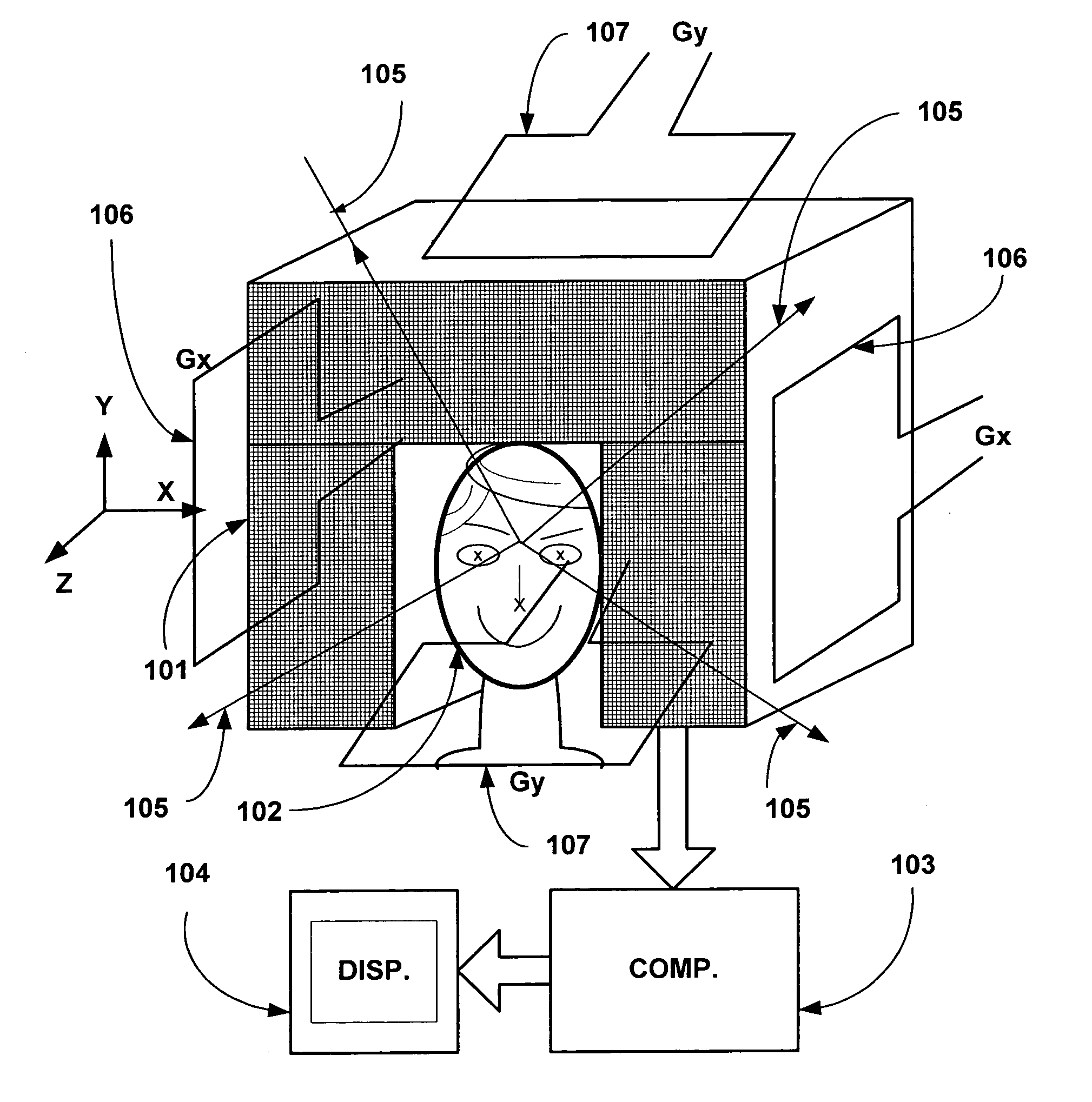
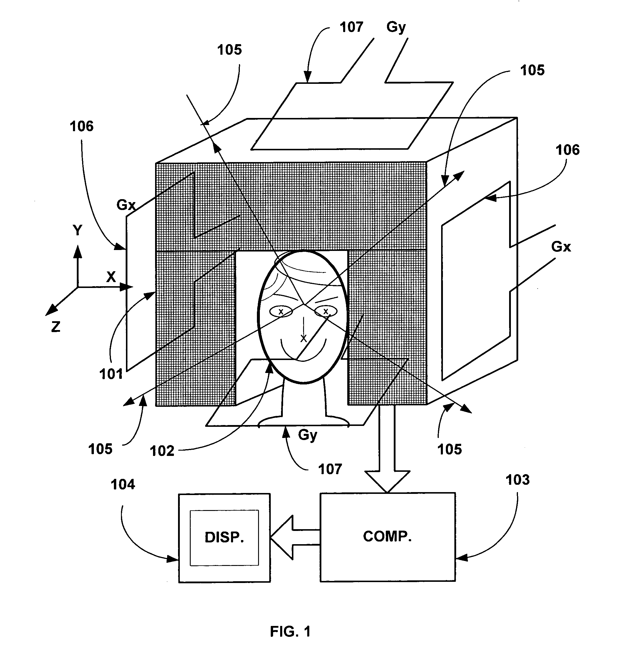
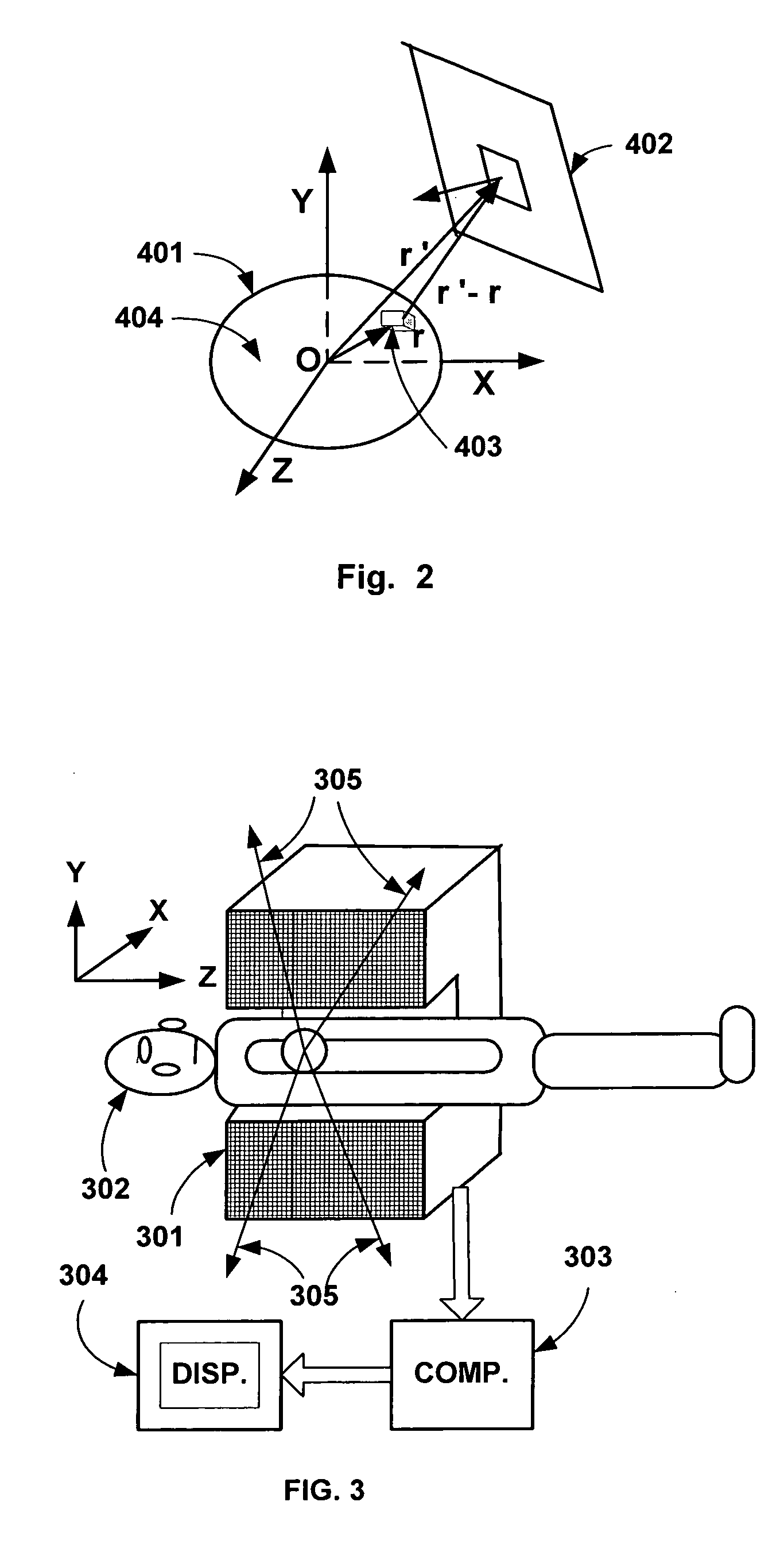
[0051]This invention discloses novel methods and apparatuses for 3D imaging of any magnetizable object such as soft-tissue. A detailed description of the methods and apparatuses are presented in this section.

[0052]The present invention is based on a new theory not found in prior art. It is based on the Field Paradigm. Therefore, the theoretical basis of the present invention is presented with concrete mathematical derivations for 3D imaging in MDI and MRI.

[0053]Magnetic Density Imaging (MDI) is a novel imaging technique related to Magnetic Resonance Imaging (MRI) but without necessarily exploiting magnetic resonance characteristics of objects. MDI provides images of objects similar to those provided by MRI in prior art. An object to be imaged by MDI is first subjected to a known polarizing magnetic field at each point for a short time duration of the order of around 0.00001 to 100.0 second (comparable to the T1 relaxation time of the target object). This causes the small volume elem...


PUM


Abstract

Three-dimensional (3D) tomographic image of a target object such as soft-tissue in humans is obtained in the method and apparatus of the present invention. The target object is first magnetized by a polarizing magnetic field pulse. The magnetization of the object is specified by a 3D spatial Magnetic Density image (MDI). The magnetic field due to the magnetized Object is measured in a 3D volume space that extends in all directions Including substantially along the radial direction, not just on a surface as in prior art. This measured data includes additional information overlooked in prior art and this data is processed to obtain a more accurate 3 D image reconstruction in lesser time than in prior art. The methods and apparatuses of the present invention are combined with frequency and phase encoding techniques of Magnetic Resonance imaging (MRI) technique in prior art to achieve different trade-offs.

Description

1. FIELD OF INVENTION[0001]Magnetic Density Imaging (MDI) is a novel imaging technique related to Magnetic Resonance Imaging (MRI). It is based on the new Field Paradigm for 3D medical imaging proposed recently by the author of this invention. MDI provides images of objects similar to those provided by Magnetic Resonance Imaging (MRI) in prior art.[0002]An object to be imaged by MDI is first subjected to a known polarizing magnetic field at each point for a short time duration of the order of around 0.00001 to 100.0 second (comparable to T1 relaxation time). This causes the nuclei in the small volume elements or voxels of the object to be magnetically polarized into small dipoles in the direction of the original polarizing magnetic field. The magnitude of polarization of each volume element is linearly related to the density of nuclear magnetic dipoles such as Hydrogen nuclei. The 3D spatial distribution of the magnetic vector field produced by the polarized object is then measured ...

Claims


Application Information

Patent Timeline
Patent Type & Authority Patents(United States)
IPC IPC(8): G01V3/14G01R33/48
CPCG01R33/445G01R33/48G01R33/448G01R33/5616
Inventor SUBBARAO, MURALIDHARA
Owner SUBBARAO MURALIDHARA
Why Eureka
Try Eureka