
Unwrapping angles from phasor measurement units

a technology of phasor and measurement unit, applied in the field of monitoring and controlling such, can solve the problems of not even realizing the existence of the unwrapping problem, and the assumption that the angles are less than 360 degrees (i.e., less than one integer cycle apart) is not always correct in the real world

Active Publication Date: 2013-06-04
OSLSOFT INC
View PDF3 Cites 20 Cited by
  • Summary
  • Abstract
  • Description
  • Claims
  • Application Information

AI Technical Summary

Benefits of technology

The present technique solves the problem of unwrapping and helps improve monitoring of grids and the use of PMUs in smart grids. It uses synchronized PMU data to enable a wide range of new applications. Additionally, it can be used directly in state estimators and can help re-synchronize islands back to the main grid. It is unique because it does not require an additional reference angle and uses the GPS clock as the reference.

Problems solved by technology

Most people, however, do not even recognize the existence of the unwrapping problem.
The assumption that angles are less than 360 degrees (i.e., less than one integer cycle apart) is not always correct in the real world.

Method used


Image

  • Unwrapping angles from phasor measurement units
  • Unwrapping angles from phasor measurement units
  • Unwrapping angles from phasor measurement units

Examples


Embodiment Construction

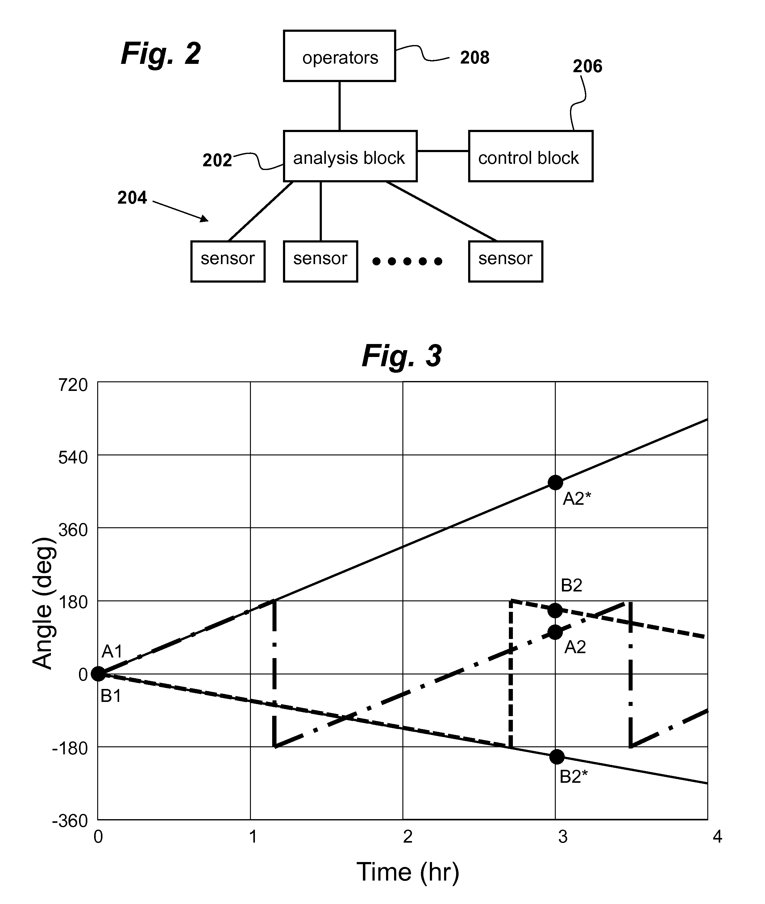
[0016]In U.S. Pat. No. 7,490,013, which is incorporated herein by reference, the present inventor disclosed a power grid failure detection system that can warn operators of impeding failures or even automatically take emergency action. As shown in FIG. 2, this system uses multiple sensors 204 to gather frequency and phase information that feed an analysis block 202 to determine grid instabilities. The power grid is monitored at one or more locations using sensors 204 that measure AC frequency. The sensors can also gather other useful data such as phase, voltage, current, and power and this invention applies to these variables also.

[0017]Analysis block 202 is connected to one or more sensors 204, typically by a remote data network. The sensors preferably have a high sampling rate, e.g., 1 Hz, 20 Hz, or 60 Hz. The higher the sampling rate, the lower the noise in the signal, especially in higher order harmonics. Optionally, the analysis block 202 may be connected to a control block 206...


PUM


Abstract

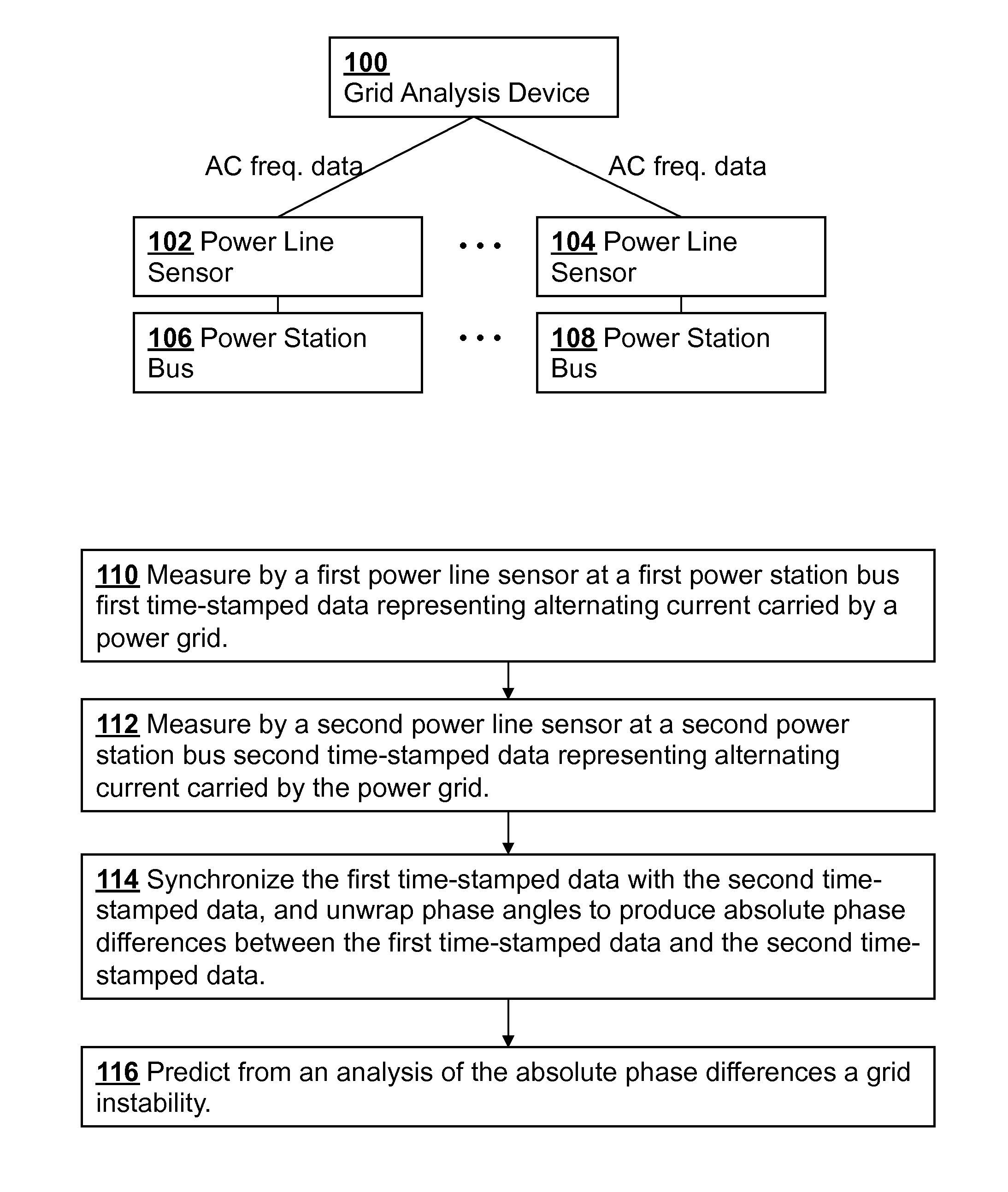
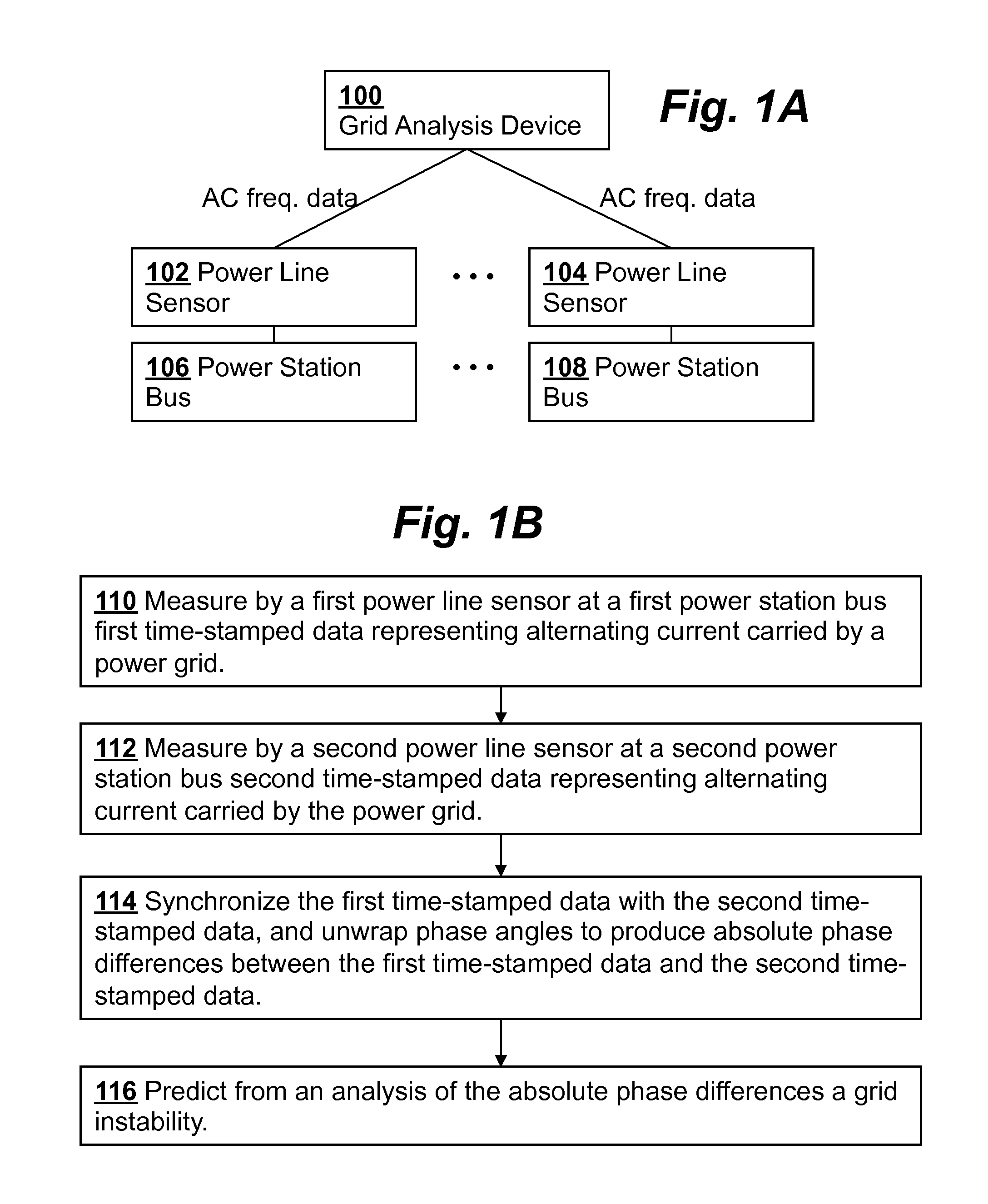
A method for monitoring a power grid uses power line sensors to measure time-stamped data representing AC current carried by the power grid at a multiple locations on the power grid, communicates the measured data from the power line sensors to a grid analysis device where the data measured by the power line sensors is synchronized and unwrapped to produce absolute phase data. The absolute phase data is then analyzed to generate predictions of instability of the power grid. The resulting unwrapped angle could also be called the “angle distance” from the reference.

Description

CROSS-REFERENCE TO RELATED APPLICATIONS[0001]This application claims priority from U.S. Provisional Patent Application 61 / 592,529 filed Jan. 30, 2012, which is incorporated herein by reference.FIELD OF THE INVENTION[0002]The invention relates to electrical power grids, and, more specifically, to methods and systems for monitoring and controlling such power grids.BACKGROUND OF THE INVENTION[0003]Electric power grids that carry electrical power to homes and businesses are sometimes prone to failure, resulting in a blackout for the affected areas. The causes for grid failure include imbalances between load and power generation.[0004]Power grids are usually monitored constantly for alternating current (AC) frequency. Power grid operators try to keep the AC frequency as close to a fixed frequency as possible. For example, the nominal AC frequency of the power grid in the US is 60 Hz, while in Europe and parts of Japan, the nominal AC frequency of the power grid is 50 Hz. While the AC fre...

Claims


Application Information

Patent Timeline
IPC IPC(8): G01R21/00
CPCH02J3/24Y02E60/728Y04S10/265Y02E60/00Y04S10/00Y04S10/22Y02E40/70H02J3/242
Inventor WELLS, CHARLES H.
Owner OSLSOFT INC
Learn More