Coaxial communication active tap device and distribution system

a technology of coaxial communication and active tap, which is applied in the direction of two-way working systems, line-transmission details, and television systems, etc., can solve the problems of a single power source providing a much larger distribution network and/or a lower overall power consumption, and achieves a large distribution network and efficient use of directional couplers. , the effect of reducing the overall power consumption

Active Publication Date: 2005-09-22
ARRIS ENTERPRISES LLC
View PDF22 Cites 22 Cited by
  • Summary
  • Abstract
  • Description
  • Claims
  • Application Information

AI Technical Summary

Benefits of technology

[0022] The present invention is directed to a low-cost active tap for use in coaxial cable communication distribution systems and characterized by low system power consumption and low signal distortion, as well as providing a technically feasible way to increase system bandwidth beyond 860 MHz.
[0024] While the active tap consumes power, these devices can be used to judicially replace conventional passive taps within a signal distribution network to obviate the need for expensive and power hungry traditional CATV repeater amplifiers, with the net result of lower overall power consumption and / or a much larger distribution network being supplied by a single power source. In general, factors for determining the number of passive and active taps that can be cascaded include: A) desired signal level at a node output; B) distance between taps; C) density of subscribers; D) size of coaxial cable; and E) efficiency of the directional coupler used in the network (e.g., DC-8, DC-12, DC-16).
[0025] Not only do these devices reduce the power required to run the system, they are also producible at much lower costs than conventional CATV repeater amplifiers (for example, line extenders, trunking amplifiers and bridging amplifiers). Active taps according to the present invention may eliminate most bridging amplifiers, trunking amplifiers and line extenders from coaxial communication networks.

Problems solved by technology

While the active tap consumes power, these devices can be used to judicially replace conventional passive taps within a signal distribution network to obviate the need for expensive and power hungry traditional CATV repeater amplifiers, with the net result of lower overall power consumption and / or a much larger distribution network being supplied by a single power source.

Method used


Image

  • Coaxial communication active tap device and distribution system
  • Coaxial communication active tap device and distribution system
  • Coaxial communication active tap device and distribution system

Examples


Embodiment Construction

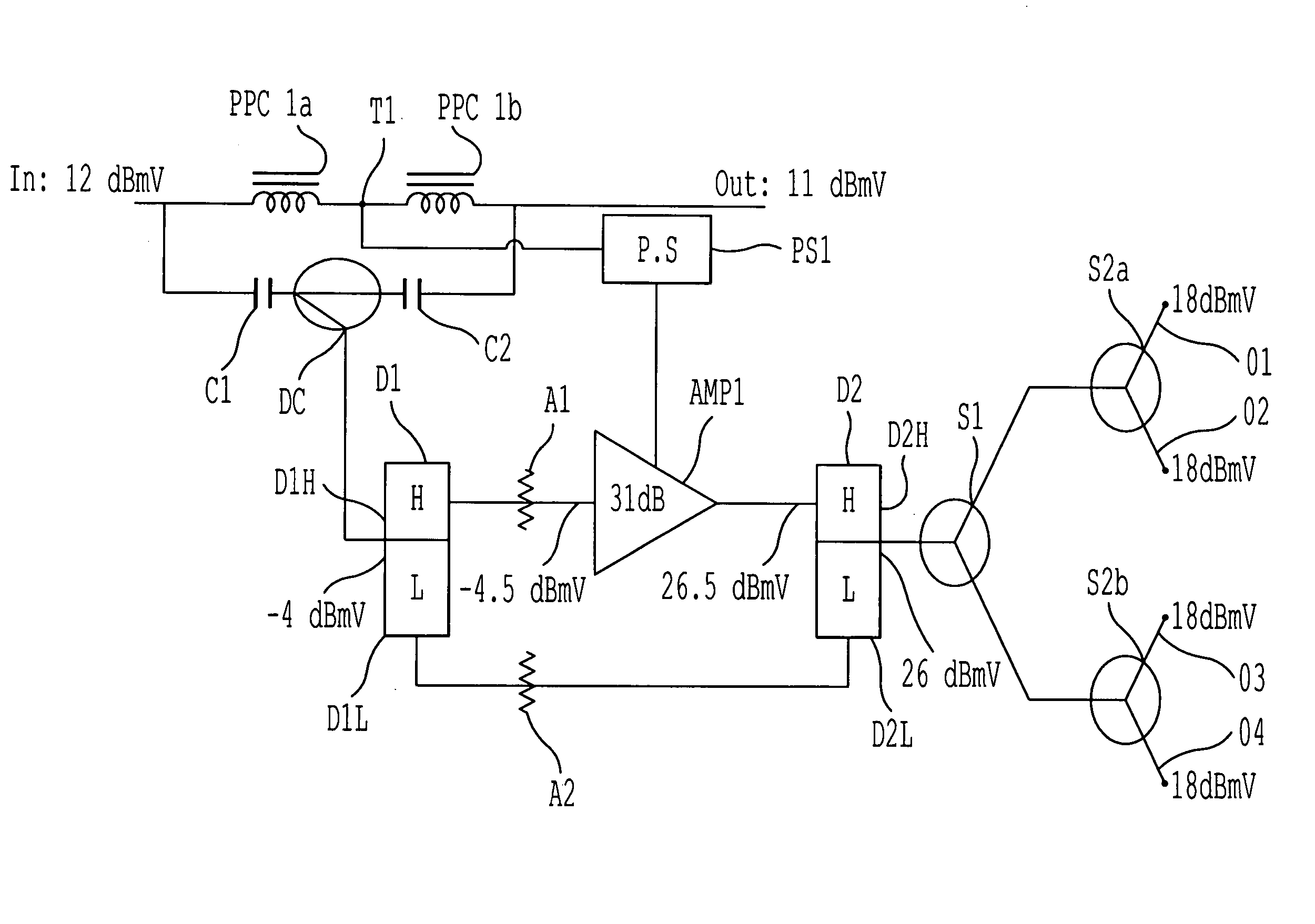
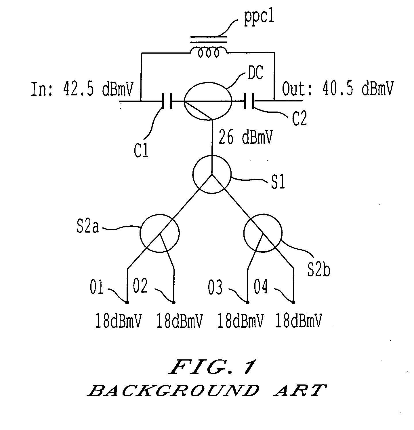
[0036]FIG. 5 shows a block diagram of an embodiment of the present invention which corresponds in function but not in operation with the conventional passive tap block diagram of FIG. 1. Here an input value of 12 dBmV is presented to a parallel circuit comprising a first power passing choke PPC1A connected to a second power passing choke PPC1B. An output tap T1 is placed between the first and second power passing chokes (PPC1A and PPC1B). Signal is passed from the output tap T1 to a power supply PS1. The output of the power supply PS1 is then fed to an amplifier AMP1. In parallel to the two power passing chokes (PPC1A and PPC1B) is a circuit, comprising: a first capacitor C1, a directional coupler DC, and second capacitor C2. The output of the directional coupler DC is fed to the combined port of a first diplex filter D1. The output of the first high-pass filter D1H is fed to the amplifier AMP1 via a first attenuator A1.

[0037] The output of the amplifier is then fed to a second hig...


PUM


Abstract

An apparatus, system, and method for affordably distributing cable communication signals at greatly reduced power consumption levels with high signal quality with an active tap having gain stage characterized by low power (less than 1 Watt), low noise figure (less than 3 dB), high bandwidth (typically 2 GHz), and high gain (at least 15 dBmV).

Description

BACKGROUND OF THE INVENTION [0001] 1. Field of Invention [0002] A low-cost active tap for use in cable communication distribution systems and characterized by low power consumption, low signal distortion, and increased reliability. [0003] 2. Summary of the Background [0004] In conventional coaxial communication distribution systems, signals are distributed along cable lines. Consumers located along the length of the cable run are supplied with signals via passive taps. FIG. 1 is a block diagram of a conventional four-port 24 dB passive tap device. The input signal flows in parallel to a power-passing choke PPC1 and to a series circuit comprising a first capacitor C1, a directional coupler DC, and a second capacitor C2. The directional coupler DC also outputs signals to a first splitter S1. This first splitter S1 feeds the signal then to a pair of second splitters S2A and S2B. The output of the second splitters S2A and S2B then flows to output ports O1, O2, O3, and O4. Signals may al...

Claims


Application Information

Patent Timeline
Patent Type & Authority Applications(United States)
IPC IPC(8): H03G3/30H03G11/04H04B3/04
CPCH03H7/46H04N7/104H04B3/04H03H11/36
Inventor PAVLIC, JOHNFOX, MARKSHUPE, VICTOR SCOTT
Owner ARRIS ENTERPRISES LLC
Why Eureka
Try Eureka