Piston having diode laser hardened primary compression ring groove and method of making the same

Inactive Publication Date: 2008-03-06
COHERENT INC
View PDF2 Cites 25 Cited by
  • Summary
  • Abstract
  • Description
  • Claims
  • Application Information

AI Technical Summary

Benefits of technology

[0016] Furthermore, the diode laser has a preferred and natural beam shape that is rectangular in shape. Accordingly, the direct diode laser can be used directly without the need for expensive integrating optics, which is required for CO2 lasers.
[0017] In accordance with an exemplary feature of the present invention, a diode or semiconductor laser is used to harden only one of the functional areas of the primary ring groove defined by the bottom or top landing of the groove surface. This hardening process significantly increases piston head longevity. The laser diode hardening process significantly reduces the distortion as compared to induction heat treating the piston, thus re-machining after laser heat treat is not required. The direct diode laser process is much more controllable and predictable as compared to induction hardening. The diode laser is a solid state laser that has no gas resonators like a CO2 laser. Therefore, the diode laser has a very high response rate. In addition, unlike CO2, the diode laser is constructed for the incoherent combination of many diode lasers, which allows for a very uniform spot without special hot spots. The diode laser also eliminates the need for environmentally unfriendly quenching fluids and eliminates the need for environmentally unfriendly paints and absorbing coatings that are used with the CO2 laser.
[0018] As compared with the traditional CO2 laser, the direct diode laser also does not require a time-consuming-application of absorption coatings. This is due to the fact that the diode laser has a wavelength that is much shorter (e.g., 800 nm, which is closer to UV), and is much more absorbing than the CO2 laser, which has a wavelength of 10.6 microns.
[0019] Furt

Problems solved by technology

A piston, such as one proposed for use in an engine, takes much abuse during its function.
Such induction hardening affects a large cross sectional area of the piston head surrounding the ring groove, hardening this volume of the piston head to no functional advantage.
Rather, such large cross sectional area hardening has been found to be detrimental to longevity of the piston, often leading to stress cracking of the dome or combustion head surface of the piston.
In addition to deforming the machined surface to cause additional time consuming grinding because the part is now hardened such that low cost machining cannot be performed.
This leads to distortion of the piston landings, which have to be held at very high tolerance for engine longevity.
Thus, the induction-hardened pistons have to go through subsequent and expensive machining

Method used


Image

  • Piston having diode laser hardened primary compression ring groove and method of making the same
  • Piston having diode laser hardened primary compression ring groove and method of making the same
  • Piston having diode laser hardened primary compression ring groove and method of making the same

Examples


Example

[0038] Referring now to the drawings, and more particularly to FIGS. 1-11, there are shown exemplary embodiments of the method and structures according to the present invention.

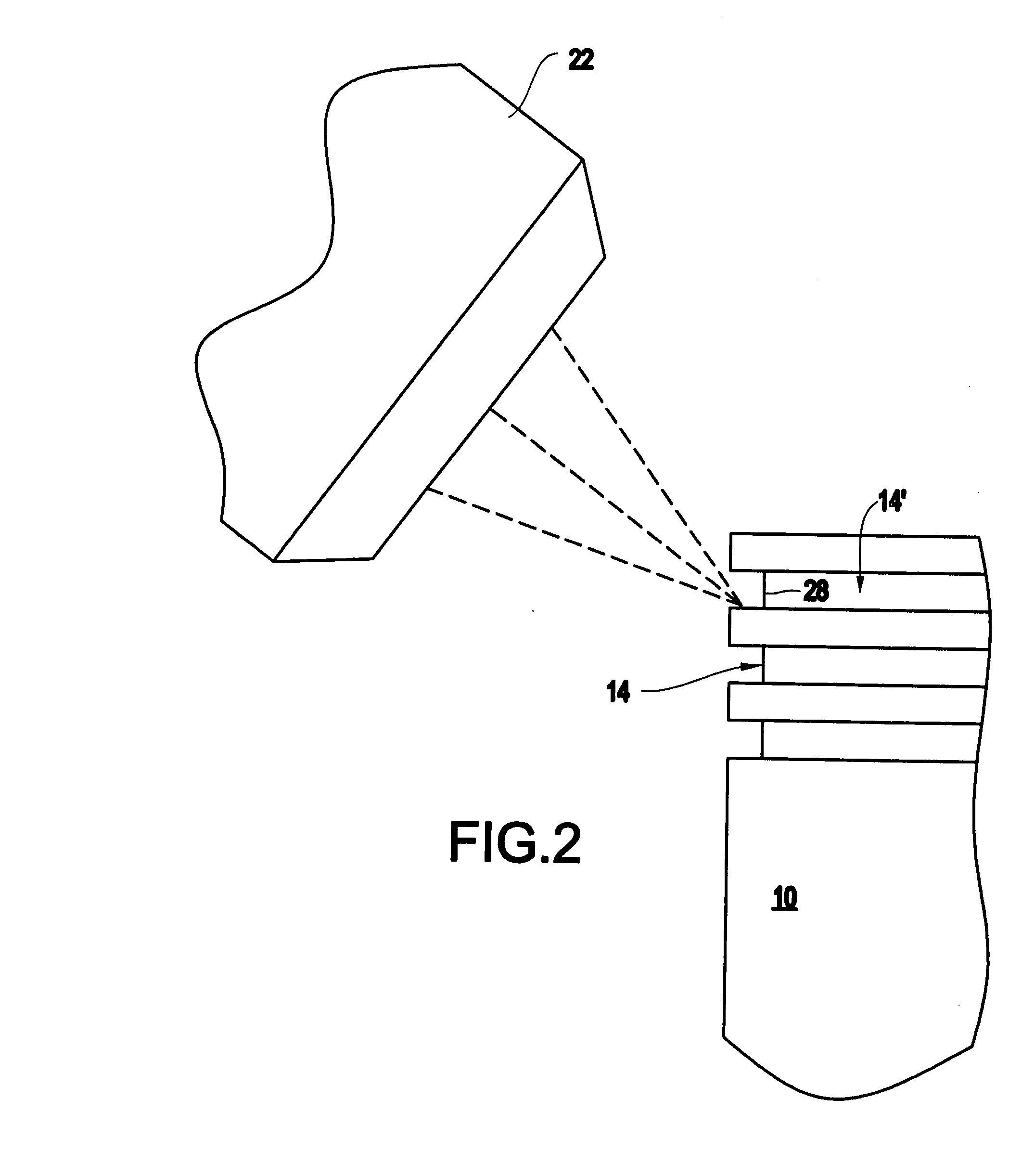
[0039] Referring now to the drawings in greater detail, there is illustrated therein a piston having a laser hardened primary compression ring groove bottom surface defining land, the piston being generally referred to by the reference numeral 10.

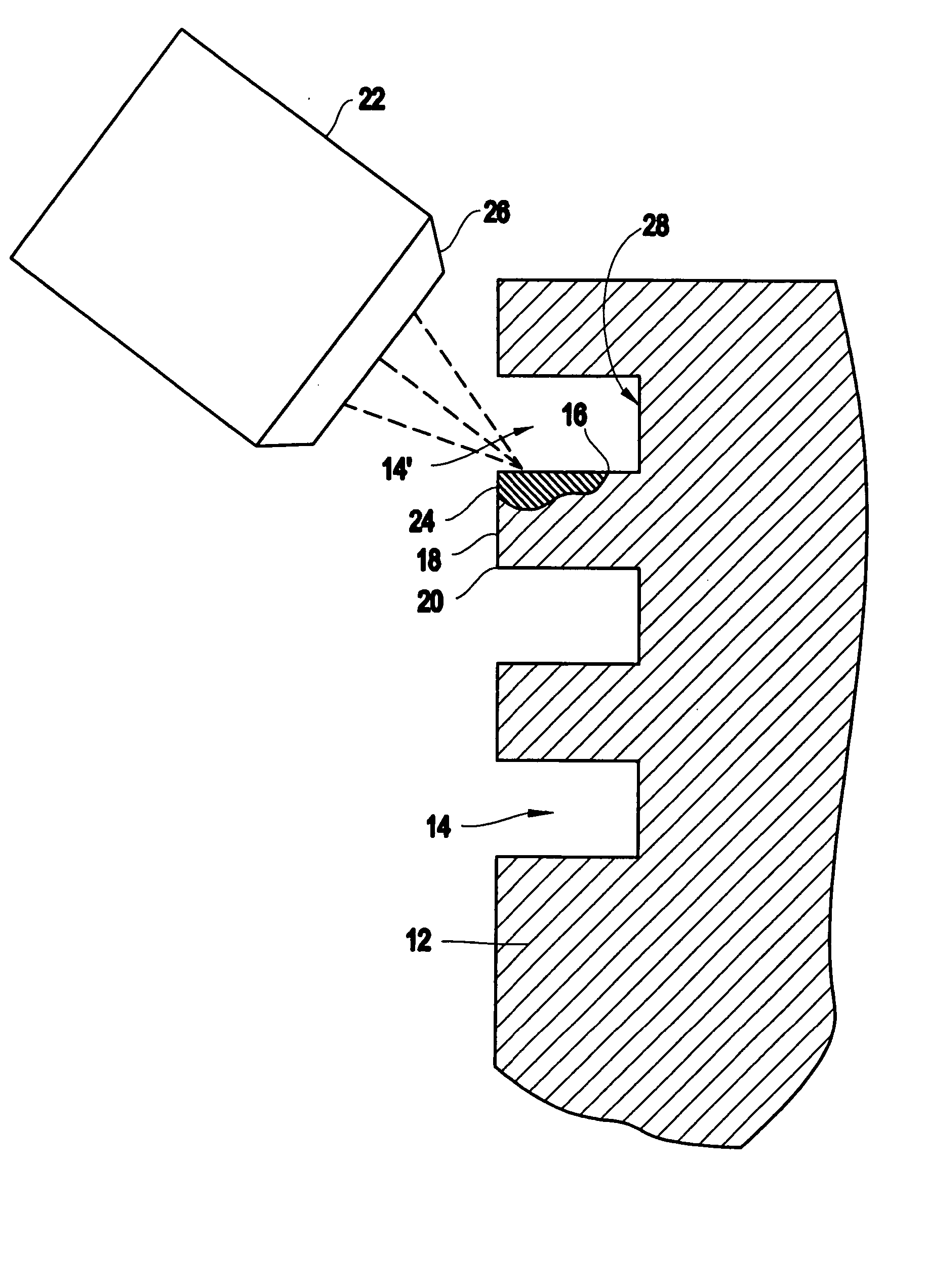
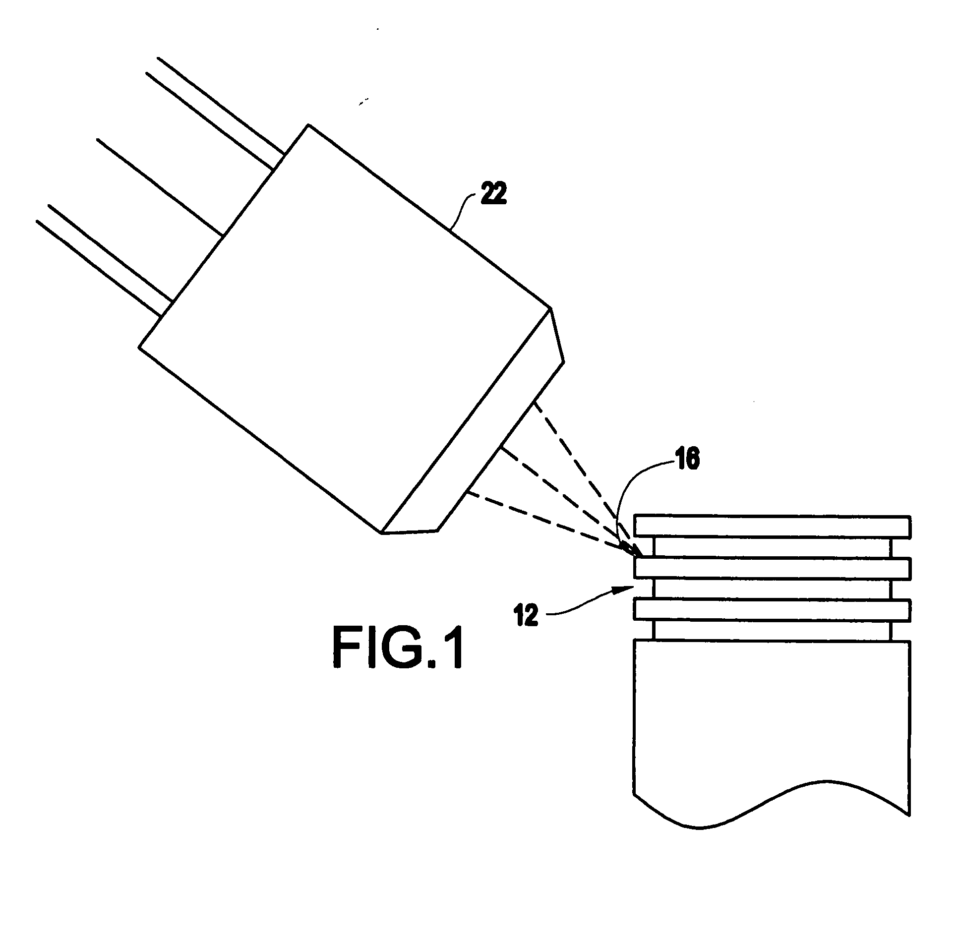
[0040] As shown in FIGS. 1-3, the piston 10 includes a head portion 12 which has a plurality of circumferential piston ring grooves 14 therein, a primary one of which is labeled 14′.

[0041] This primary groove 14′ has a bottom surface 16 which is defined by a primary land 18, the land 18 having chamfered outer corners 20.

[0042] Presently, the area of the piston head 12 incorporating this primary compression ring groove 14′ is hardened by the process of induction. Such induction hardening causes a brittleness and distortion of the metal material, leading to crackin...


PUM

PropertyMeasurementUnit
Timeaaaaaaaaaa
Areaaaaaaaaaaa

Abstract

A piston having a head includes a circumferential compression ring groove having a top surface, a bottom surface and an inset rear wall extending between the top surface and the bottom surface, wherein a confined area of the compression ring groove is hardened.

Description

CROSS REFERENCE TO RELATED APPLICATIONS [0001] The present application is related to U.S. Provisional Patent Application No. 60 / 839,412 filed on Aug. 23, 2006, to Corgan et al., entitled “PISTON HAVING DIODE LASER HARDENED PRIMARY COMPRESSION RING AND METHOD OF MAKING SAME”, which is incorporated, in its entirety, herein by reference.BACKGROUND OF THE INVENTION [0002] 1. Field of the Invention [0003] The present invention relates to a piston having a hardened primary compression ring groove and the method of making same. More particularly, the invention relates to the use of a diode laser in hardening surfaces of the primary groove of a piston. [0004] 2. Description of the Related Art [0005] A piston, such as one proposed for use in an engine, takes much abuse during its function. Further, to keep forces of combustion taking place against a head of the piston, from escaping around the piston, a plurality of compression rings are seated about the circumference of the piston, each rin...

Claims


Application Information

Patent Timeline
IPC IPC(8): F01C1/07B23K26/00C21D1/09
CPCC21D1/09Y10T29/49254F16J9/00
Inventor HAAKE, JOHN M.CORGAN, KEVIN
Owner COHERENT INC
Why Eureka
Try Eureka