Turbomachine

a technology of rotating motors and rotating shafts, which is applied in the direction of machines/engines, mechanical apparatus, liquid fuel engines, etc., can solve the problems of affecting the operation of the engine, so as to avoid the damage of thermal stratification

Inactive Publication Date: 2008-02-12
ANSALDO ENERGIA SWITZERLAND AG
View PDF20 Cites 26 Cited by
  • Summary
  • Abstract
  • Description
  • Claims
  • Application Information

AI Technical Summary

Benefits of technology

[0007]The essence of the invention is therefore for means which are suitable for specifically imposing a forced and preferably directional convection with a predominant circumferential component on the fluid inside a cavity directly in the cavity itself. The cavity in this case is formed in particular between an inner casing and an outer casing of the turbomachine, thus, for example, between a combustor wall and an outer casing of a gas turbine. In this case, the cavity is designed with an essentially annular cross section, in particular as a torus, or with a cross section in the shape of a ring segment. On account of the high thermal loading during operation of the turbomachine, it is advantageous if the means for driving the flow have no movable parts. The direct use of blowers, fans and devices of that kind having movable parts is therefore advantageously to be avoided inside the cavity for driving the convection flow. At least one ejector which can be operated with a motive fluid is preferably provided inside the cavity. Within the scope of the invention, an ejector may readily also be, for example, a tangentially oriented hole which is arranged in a casing wall and which is able to introduce a directional flow into the cavity. Ejectors require only a small mass flow of motive fluid in order to drive and maintain a flow sufficient for the intended purpose at, for example, 8 m / s to 20 m / s inside the cavity. This limiting of the mass flow of the motive medium is important especially when existing auxiliary systems are to be utilized for driving the flow, these auxiliary systems delivering cold fluid, for example external air, into the cavity. Furthermore, the ejectors have the advantage of being able to set a directional circulating flow in such a way that, in addition to the predominant circumferential component, an axial component is also imposed on the flow brought about. This has the further advantage that axial temperature differences in axially extended cavities can also be evened out.
[0008]In a preferred embodiment of the invention, the cavity is provided with an extraction point which is connected to the ejector via a blower which can be arranged outside the region of high thermal loading. This blower delivers a motive fluid in a closed circuit from the extraction point to the ejector. The temperature gradient of a turbine casing can therefore be markedly reduced, which also improves the safety and reliability of a warm start possibly to be realized.
[0010]If the cavity has an annular cross section, means for exciting and maintaining the through flow are preferably configured and arranged in such a way that the flow is inclined in the axial direction relative to the circumferential direction by less than 30°, in particular preferably less than 10°. Thus ejectors are preferably oriented with their blowout direction essentially in the circumferential direction. A setting of up to about 30° in the axial direction can possibly result in advantages, since in this way, in an axially extended cavity, the axial temperature distribution is also made more uniform. In particular, it is advantageous with regard to the intensity of the flow excitation if two or more ejectors oriented in the same blowout direction are arranged equidistantly at the circumference of the cavity. If these ejectors are arranged in the closed circuit as described, it is also advantageous to place the extraction point, assigned to an ejector, of the cavity, relative to the blowout direction of an ejector, directly upstream of an ejector arranged at another circumferential position. In this case, it can again be advantageous to arrange the extraction point at a different axial position from the ejector assigned to said extraction point; this measure is also perfectly suitable for helping to make the temperatures more uniform.

Problems solved by technology

It is caused by the large and high-mass structures of such machines having stored large quantities of heat after prolonged operation.
During the cooling, a pronounced vertical thermal stratification occurs in the comparatively large flow passages, this thermal stratification leading to nonuniform temperature distributions in the static and the rotating components, which, on account of the different thermal expansions, results in a distortion of casing and rotor and in deviations from the rotationally symmetrical desired geometry.
As a result, with the unavoidably small gap dimensions in modern turbomachines, jamming of the rotor in the casing occurs, which inhibits the start-up availability and in addition is capable of putting the mechanical integrity at risk.

Method used


Image

  • Turbomachine
  • Turbomachine
  • Turbomachine

Examples


Embodiment Construction

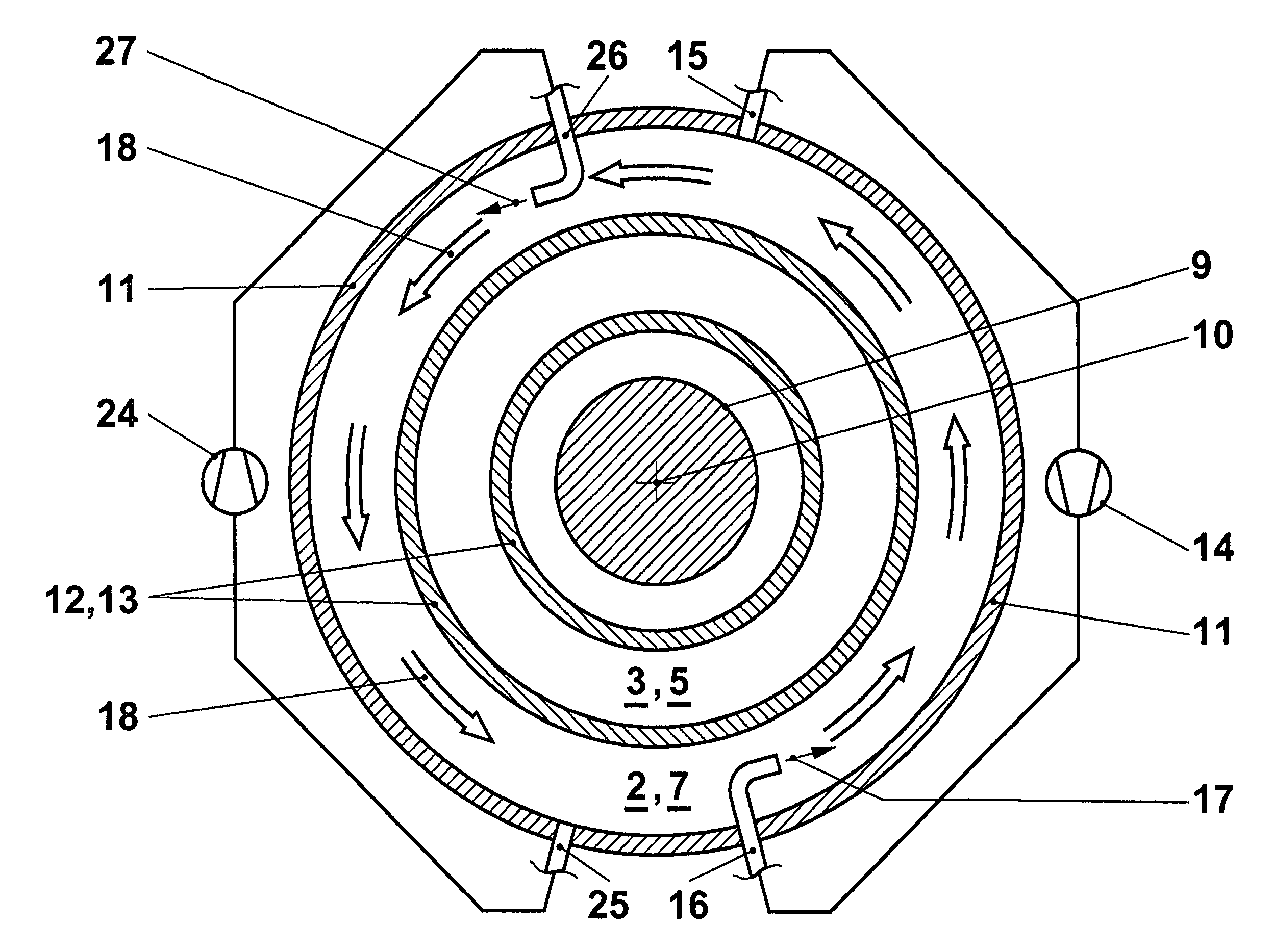
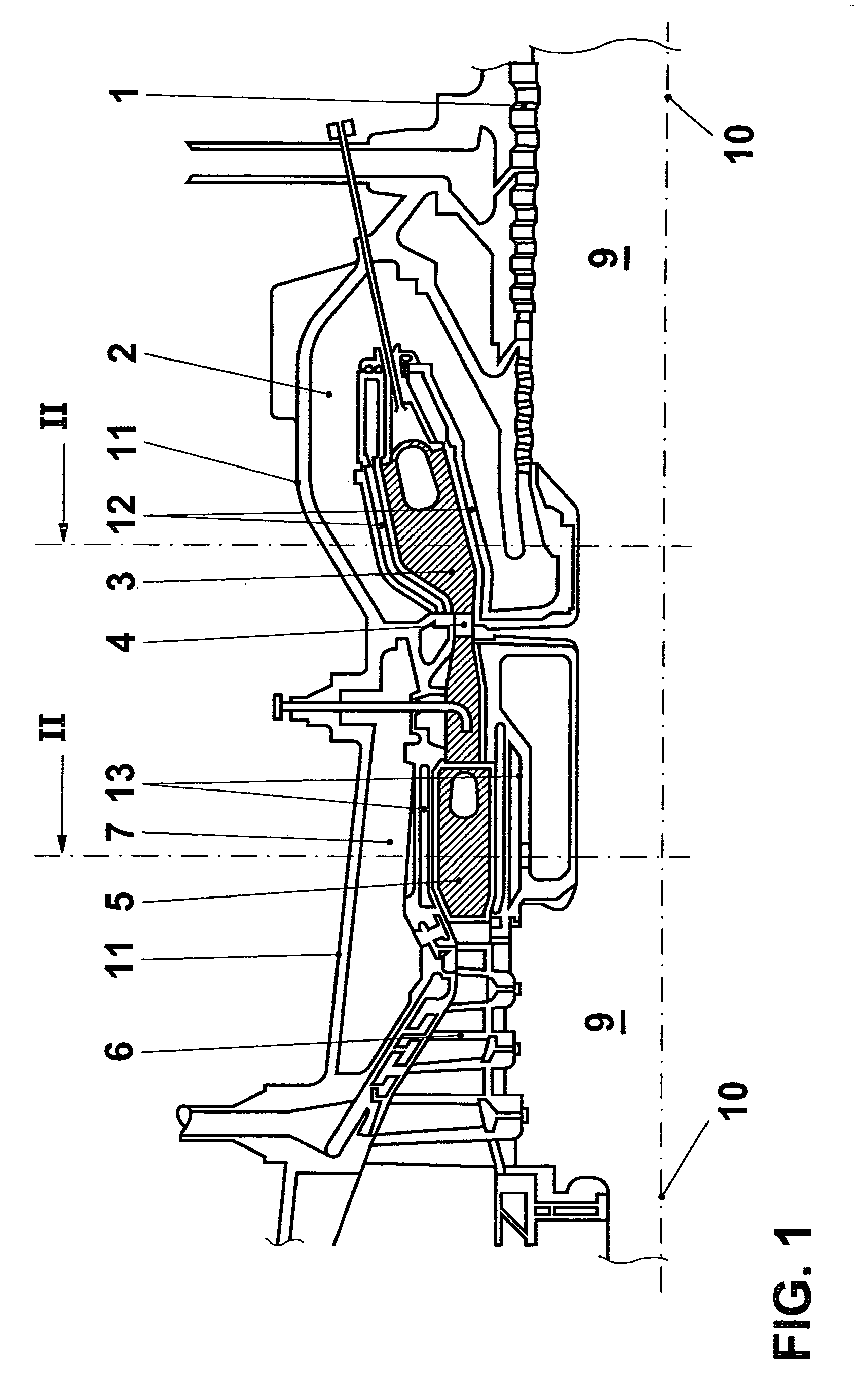
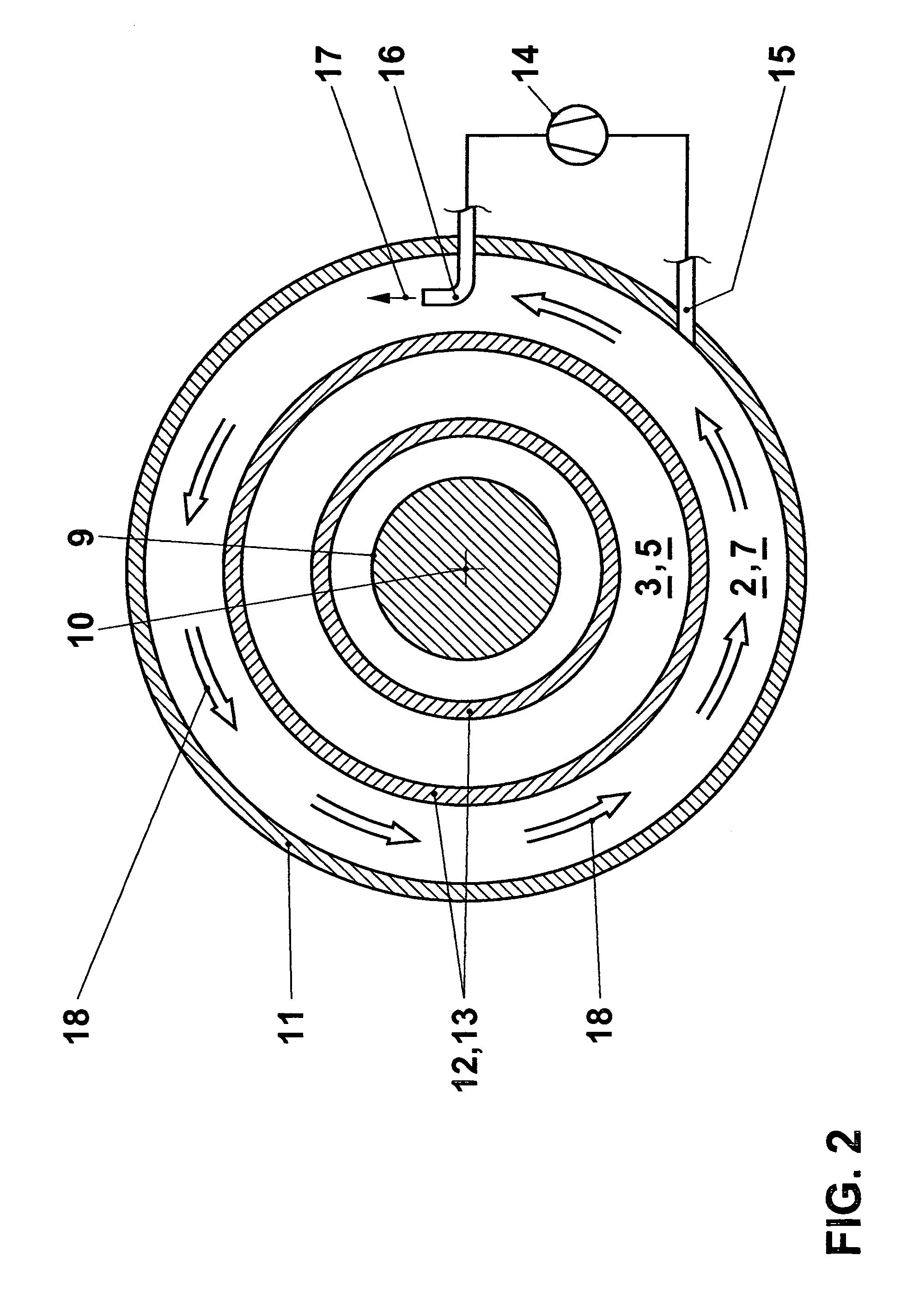
[0020]The invention is to be explained in the context of a turbomachine. The thermal block of a gas turbine is illustrated in FIG. 1, only the part above the machine axis 10 being shown. The machine shown in FIG. 1 is a gas turbine having “sequential combustion”, as disclosed, for example, by EP 620362. Although its functioning is not of primary significance for the invention, this may be explained in broad outline for the sake of completeness. A compressor 1 draws in an air mass flow and compresses it to a working pressure. The compressed air flows through a plenum 2 into a first combustor 3. A fuel quantity is introduced there and burned in the air. The hot gas produced is partly expanded in a first turbine 4 and flows into a second combustor 5, an “SEV combustor”. The fuel supplied there ignites on account of the still high temperature of the partly expanded hot gas. The reheated hot gas is expanded further in a second turbine 6, in the course of which mechanical output is transm...


PUM


Abstract

Suitable means for driving a flow are arranged in annular or ring-segment-shaped cavities that are formed in particular in multi-shell casings of turbomachines. Arranged inside the cavity are ejectors that are supplied via suitable means with a motive-fluid flow which in turn excites the flow, preferably a circumferential flow or a helical flow. The invention is suitable in particular for avoiding casing distortions when turbomachines are at rest.

Description

CROSS-REFERENCE TO RELATED APPLICATIONS[0001]This application is a continuation of the U.S. National Stage designation of co-pending International Patent Application PCT / IB02 / 02884 filed Jul. 22, 2002, the entire content of which is expressly incorporated herein by reference thereto.FIELD OF THE INVENTION[0002]The present invention relates to a turbomachine and a method of operating such a turbomachine.BACKGROUND OF THE INVENTION[0003]The phenomenon of the “buckling” of the rotor and of the casing of turbomachines such as gas turbines and steam turbines is sufficiently known. It is caused by the large and high-mass structures of such machines having stored large quantities of heat after prolonged operation. During the cooling, a pronounced vertical thermal stratification occurs in the comparatively large flow passages, this thermal stratification leading to nonuniform temperature distributions in the static and the rotating components, which, on account of the different thermal expa...

Claims


Application Information

Patent Timeline
Patent Type & Authority Patents(United States)
IPC IPC(8): F01D25/26F01D25/12
CPCF01D25/12F01D25/26F05D2260/601Y02T50/60
Inventor DITTMANN, ROLFHURTER, JONASMARMILIC, ROBERTMEYLAN, PIERREPAULI, ERNST
Owner ANSALDO ENERGIA SWITZERLAND AG
Why Eureka
Try Eureka