Electronic ohmic shunt RF MEMS switch and method of manufacture

a microelectromechanical system and switch technology, applied in selector switches, relays, relays, etc., can solve the problems of 10 ghz, inadequate performance below x-band, subject to their own failure mechanisms, etc., and achieve the effect of reducing parasitic inductance and excess capacitan

Inactive Publication Date: 2013-06-11
UNITED STATES OF AMERICA THE AS REPRESENTED BY THE SEC OF THE ARMY
View PDF18 Cites 19 Cited by
  • Summary
  • Abstract
  • Description
  • Claims
  • Application Information

AI Technical Summary

Benefits of technology

[0015]Another embodiment provides a method of manufacturing an electrostatic ohmic shunt RF MEMS switch, wherein the method comprises forming a CPW transmission line comprising a plurality of slots and a plurality of pillars, wherein a space between successive ones of the plurality of pillars is defined by one of the plurality of slots; positioning a plurality of electrodes in the slots; elevating a conductive contact beam over the CPW transmission line and the plurality of electrodes; and positioning a plurality of conductive contact dimples between the conductive contact beam and the CPW transmission line, wherein the plurality of pillars are adapted to prevent physical contact between the plurality of electrodes and the conductive contact beam.

Problems solved by technology

Many successful switches of this kind have been demonstrated over the years but, generally, all inherently suffer from inadequate performance below X-band (<10 GHz) and are subject to their own failure mechanisms.
However, physical contact still occurs between the actuation electrodes and the contact beam; an undesirable trait with respect to switch lifetime.
The inductance of such a design also tends to hamper the high frequency operation of the switch.
Moreover, the lack of rigid mechanical constraints within the hinge region tends to make this design exceedingly susceptible to performance degradation due to vibration or even simple rigid body motion of the parent system and limits its attainable switching speed.
The lack of rigid mechanical constraints within the hinge region also, in all likelihood, results in significant device-to-device performance variability.
All of these factors tend to limit the operational lifetime of the switch as well as its usefulness in military applications.
This leads to significant degradation in the return loss of the switch, particularly at higher frequencies.
The presence of this metal in the CPW gaps prevents proper impedance matching over a large range of frequencies and contributes to low return loss.

Method used


Image

  • Electronic ohmic shunt RF MEMS switch and method of manufacture
  • Electronic ohmic shunt RF MEMS switch and method of manufacture
  • Electronic ohmic shunt RF MEMS switch and method of manufacture

Examples


Embodiment Construction

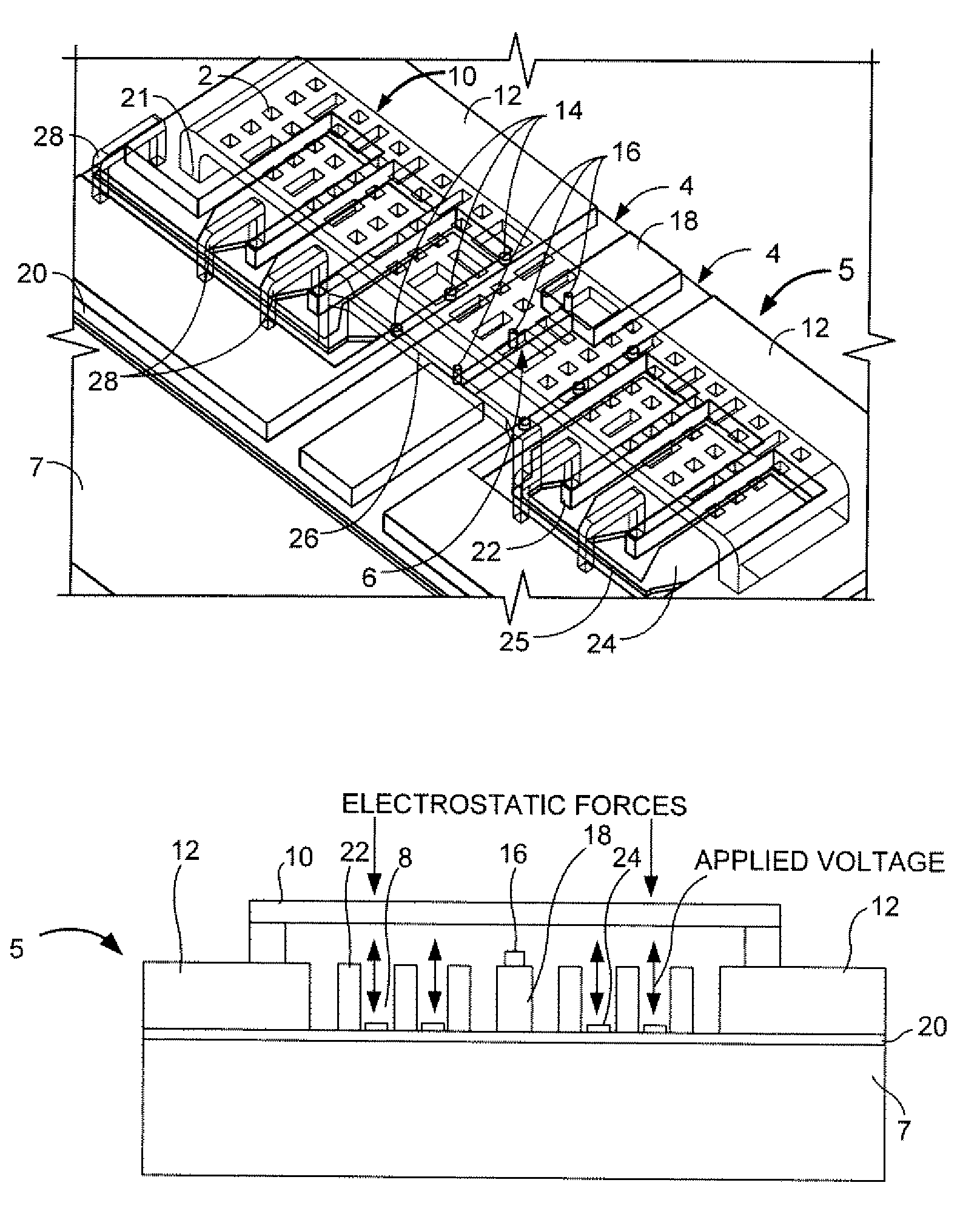
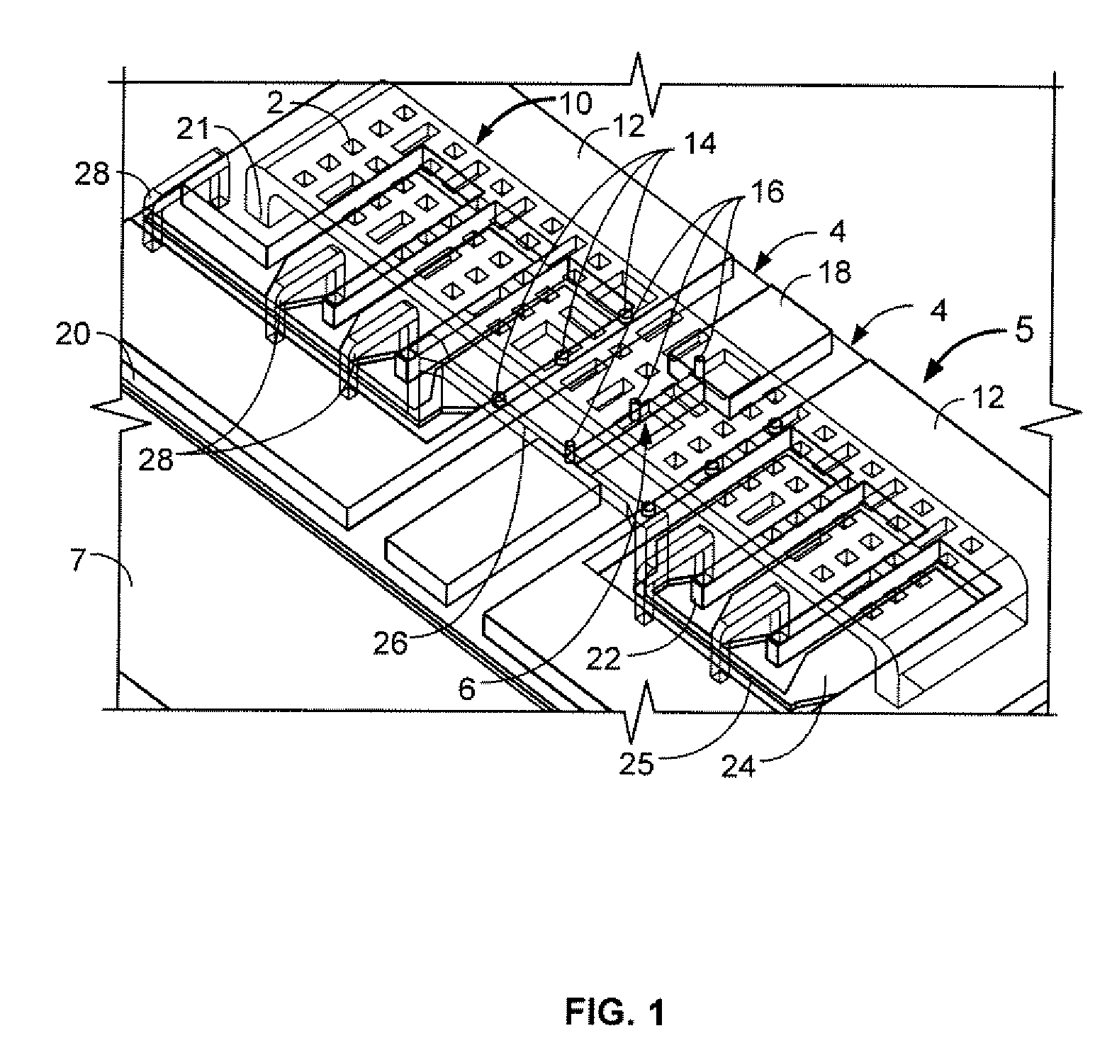
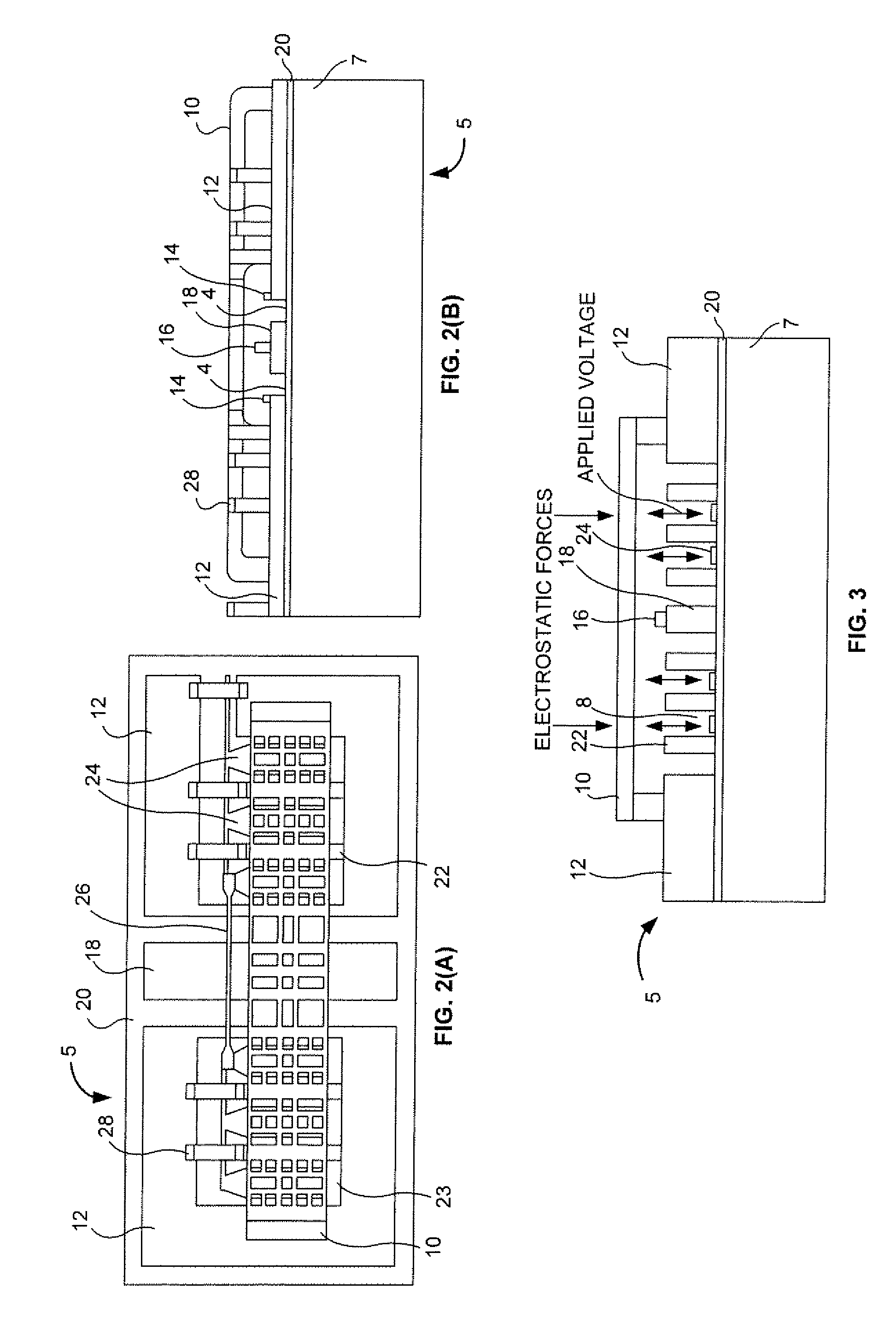
[0029]The embodiments herein and the various features and advantageous details thereof are explained more fully with reference to the non-limiting embodiments that are illustrated in the accompanying drawings and detailed in the following description. Descriptions of well-known components and processing techniques are omitted so as to not unnecessarily obscure the embodiments herein. The examples used herein are intended merely to facilitate an understanding of ways in which the embodiments herein may be practiced and to further enable those of skill in the art to practice the embodiments herein. Accordingly, the examples should not be construed as limiting the scope of the embodiments herein.

[0030]As mentioned, there remains a need for a new electrostatic ohmic shunt RF MEMS switch that achieves an improved insertion loss performance over conventional switches. The embodiments herein achieve this by providing an electrostatic ohmic shunt RF MEMS switch that has an extremely low, ne...


PUM

PropertyMeasurementUnit
impedanceaaaaaaaaaa
widthaaaaaaaaaa
widthaaaaaaaaaa

Abstract

An electrostatic ohmic shunt radio frequency (RF) microelectromechanical system (MEMS) switch and method of manufacturing includes a co-planar waveguide (CPW) transmission line comprising a plurality of slots and a plurality of pillars, wherein a space between successive ones of the plurality of pillars is defined by one of the plurality of slots; a plurality of electrodes positioned in the slots; a conductive contact beam elevated over the CPW transmission line and the plurality of electrodes; and a plurality of conductive contact dimples positioned between the conductive contact beam and the CPW transmission line, wherein the plurality of pillars are adapted to prevent physical contact between the plurality of electrodes and the conductive contact beam.

Description

GOVERNMENT INTEREST[0001]The embodiments described herein may be manufactured, used, and / or licensed by or for the United States Government.BACKGROUND[0002]1. Technical Field[0003]The embodiments herein generally relate to microelectronic systems, and, more particularly, to radio frequency (RF) microelectromechanical systems (MEMS) switches.[0004]2. Description of the Related Art[0005]RF MEMS switches have recently received considerable attention. Generally desirable for their extremely low insertion loss, extreme linearity, minimal intermodulation product generation, and power consumption characteristics; RF MEMS switches posses many advantages over their competing technologies. RF MEMS switches fall into two basic categories: series / shunt RF configurations, and ohmic / capacitive contact behaviors. RF MEMS series switches have been demonstrated with both ohmic and capacitive contacts.[0006]However, the majority of RF MEMS shunt switches have been configured with capacitive contact a...

Claims


Application Information

Patent Timeline
Patent Type & Authority Patents(United States)
IPC IPC(8): H01H51/22
CPCH01H59/0009Y10T29/49105
Inventor PULSKAMP, JEFFREY S.JUDY, DANIEL C.POLCAWICH, RONALD G.
Owner UNITED STATES OF AMERICA THE AS REPRESENTED BY THE SEC OF THE ARMY
Why Eureka
Try Eureka