Power supply apparatus including fan for air cooling

a technology of power supply apparatus and fan, which is applied in the direction of lighting and heating apparatus, electric apparatus casings/cabinets/drawers, instruments, etc., can solve the problems of inability to easily cool electronic components located away from the fan, low flexibility of electronic components arrangement, and dust entering the air path

Active Publication Date: 2013-06-11
DAIHEN CORP
View PDF39 Cites 25 Cited by
  • Summary
  • Abstract
  • Description
  • Claims
  • Application Information

AI Technical Summary

Benefits of technology

[0019]Preferably, the fan-opposed wall constitutes a casing cover for protecting the interior of the apparatus.

Problems solved by technology

In the case of using such a power supply apparatus in an environment with a lot of dust, such as a factory, dust tends to enter the air path and accumulates inside the air path.
Therefore, the conventional power supply apparatus has a drawback in that any electronic components located away from the fan cannot be easily cooled.
It also has a drawback in that the flexibility of arrangement of electronic components is not very high since a plurality of electronic components that are to be cooled need to be arranged in such a manner that those with a higher likelihood of generating heat are arranged closer to the fan.
Moreover, during a dust removal operation, compressed air that has been jetted to the interior of the air path tends to directly strike the fan located at one end of the air path, which may cause the fan to be rotated in reverse at high speed and be damaged.
In addition, the above-described conventional power supply apparatus has only a single air path.
When a plurality of electronic components having different heat-generating properties are arranged in that air path, this arrangement significantly affects the temperature and the flow of air draft, resulting in the problem that each of the electronic components cannot be cooled efficiently.
With this power supply apparatus, the opening is located in front of the fan, and therefore dust floating in the vicinity of the opening can easily be sucked in by the fan, resulting in the problem that dust can easily enter the welding power supply portion.

Method used


Image

  • Power supply apparatus including fan for air cooling
  • Power supply apparatus including fan for air cooling
  • Power supply apparatus including fan for air cooling

Examples


Embodiment Construction

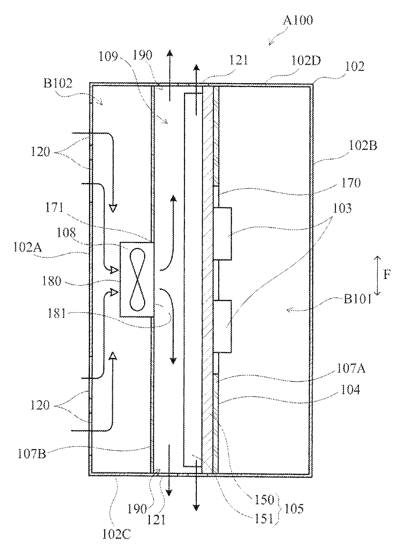
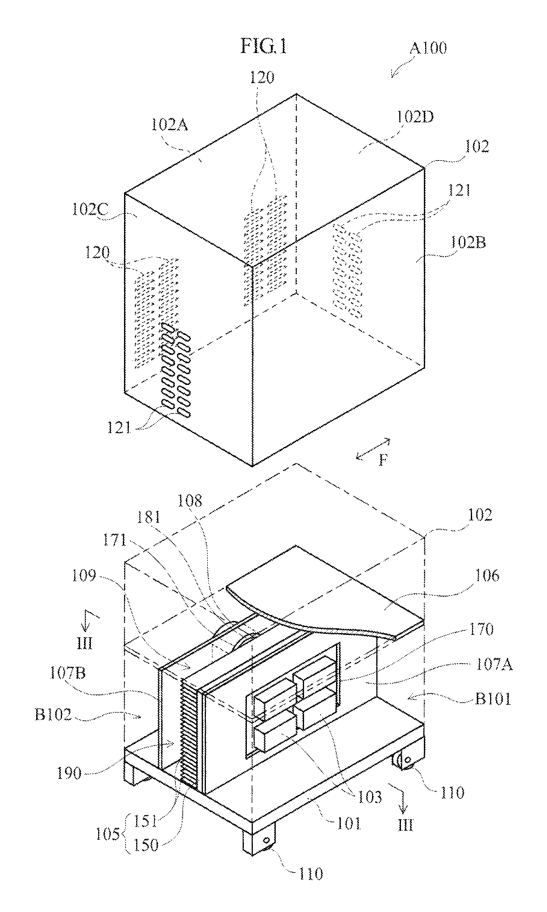
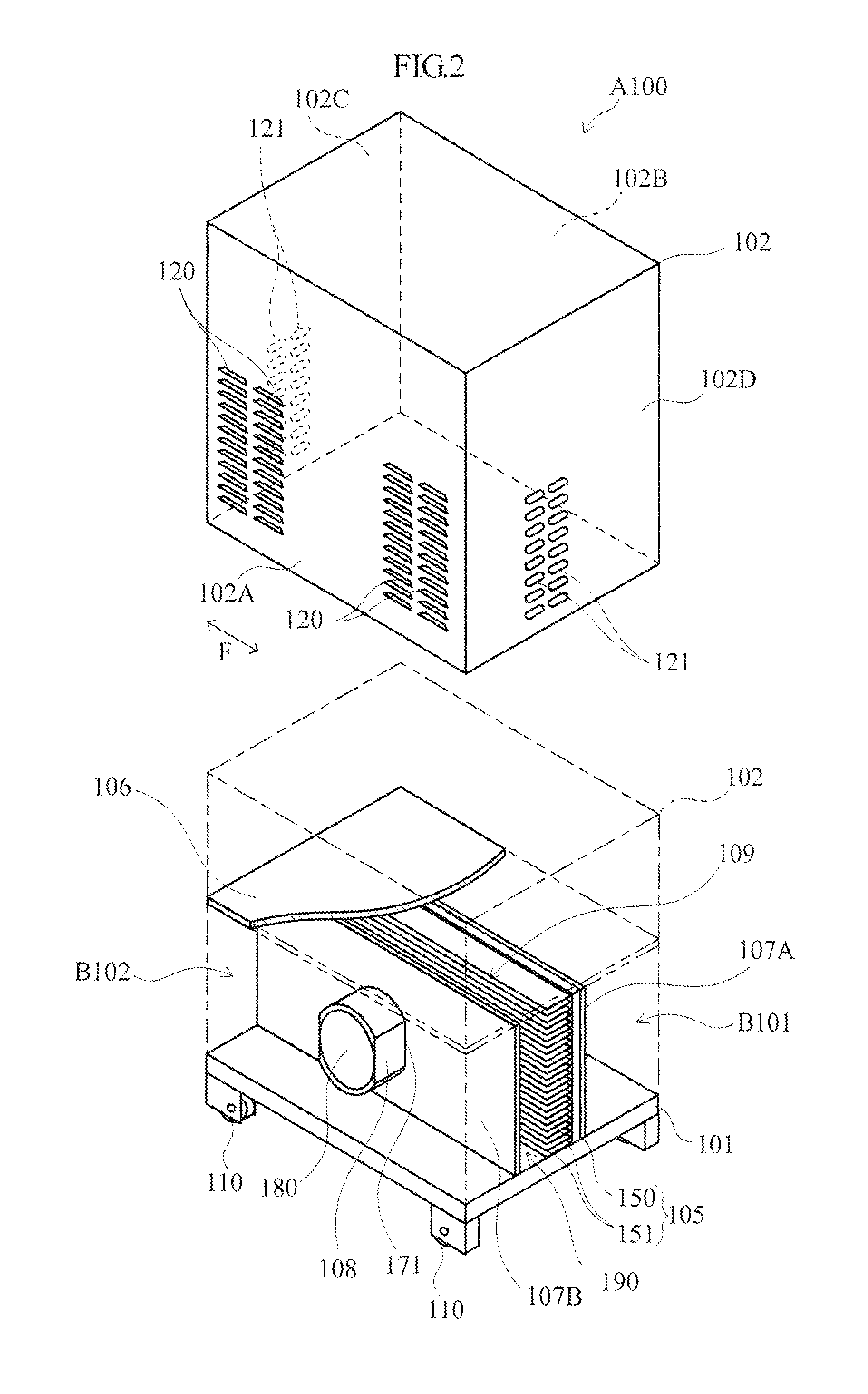
[0061]FIGS. 1 to 3 show one embodiment of a power supply apparatus. A power supply apparatus A100 of this embodiment is used, for example, for outputting large current and high voltage necessary for arc welding. The power supply apparatus A100 is used in, for example, an environment with a lot of dust, such as a factory.

[0062]The power supply apparatus A100 includes a base member 101, a casing cover 102, various electronic components 103 constituting a power circuit, a heat sink 105, a first parting plate 106, two second parting plates 107A and 107B, and a cooling fan 108. Inside the apparatus, a hollow air path 109 is provided that is surrounded by part of the base member 101, part of the first parting plate 106, and the second parting plates 107A and 107B. The air path 109 extends longitudinally in the front-rear direction of the power supply apparatus A100 (hereinafter, referred to as “F direction”). Additionally, a layout space B101 for the electronic components 103 and a layout...


PUM

PropertyMeasurementUnit
internal temperatureaaaaaaaaaa
temperatureaaaaaaaaaa

Abstract

A power supply apparatus includes an air path extending longitudinally, a fan that blows air into the air path in a direction intersecting a longitudinal direction of the air path, and a plurality of electronic components arranged in the longitudinal direction. Each of the electronic components is cooled by air passing through the air path. With this configuration, it is possible to efficiently cool the electronic components without compromising the flexibility of arrangement of the various electronic components. Also, a dust removal operation can be readily performed without the possibility of damaging the fan.

Description

BACKGROUND OF THE INVENTION[0001]1. Field of the Invention[0002]The present invention relates, for example, to a welding power supply apparatus, and particularly to a welding power supply apparatus provided with a fan for air cooling.[0003]2. Description of Related Art[0004]JP 2008-229644A discloses an example of a conventional welding power supply apparatus. The power supply apparatus disclosed in the document includes a plurality of electronic components, an air path extending longitudinally, and a fan that blows air draft into this air path. The plurality of electronic components are arranged along a side wall of the air path, and the fan is provided at one end of the air path. Air draft that has been blown into the air path by the fan blows out from an exit provided at the other end of the air path, while drawing heat away from the electronic components. As compared to electronic components that do not tend to generate heat (for example, a chip-type semiconductor device and the ...

Claims


Application Information

Patent Timeline
Patent Type & Authority Patents(United States)
IPC IPC(8): H05K7/20
CPCB23K9/1006
Inventor NAGAMI, KAZUTOSHIDOI, TOSHIMITSUMANABE, HARUHIKOTAJIMA, HIROTSUNEETOH, TETSUYAKUREHA, MASAYOSHIGAMOU, ISAMU
Owner DAIHEN CORP
Why Eureka
Try Eureka