
Flexible tubular underwater pipe for great depths, and method for manufacturing same

a tubular underwater pipe and flexible technology, applied in the direction of flexible pipes, pipes, mechanical equipment, etc., can solve the problems of increasing the risk increasing the cost of aramid fiber reinforcement tapes, so as to reduce the possibility of inflation, reduce the number of strips, and the effect of high alarm angl

Active Publication Date: 2016-07-26
TECH FRANCE SA
View PDF11 Cites 4 Cited by
  • Summary
  • Abstract
  • Description
  • Claims
  • Application Information

AI Technical Summary

Benefits of technology

The invention relates to a method of protecting pipes from inflation of armors (hose-like structures) during extreme water depth and dynamic stress conditions. The method involves using a holding layer to prevent leakage and an anti-inflation layer to reduce inflation of the armors. The inflation is reduced without increasing the number or cost of the protective strips, making the pipe more stable and resistant to lateral buckling. The method is particularly useful for pipes with high armor angling. Additionally, the invention improves the resistance to axial compression of the pipe and reduces the number of layers of protective strips needed.

Problems solved by technology

This effect tends to shorten the pipe.
Consequently, in the absence of an additional means designed to limit this inflation, the wires that make up the pulling armor plies may buckle according to a radial mode, which may cause an irreversible local deformation of said layers of armor wires, which take on a “bird cage” shape.
However, this solution has a number of drawbacks.
First of all, these aramid fiber-reinforced tapes are very costly.
Furthermore, this solution does not totally solve the problem of lateral buckling of the armor wires, notably when the pipe is simultaneously subjected to variations of curvature, notably in proximity to the sea bed.

Method used

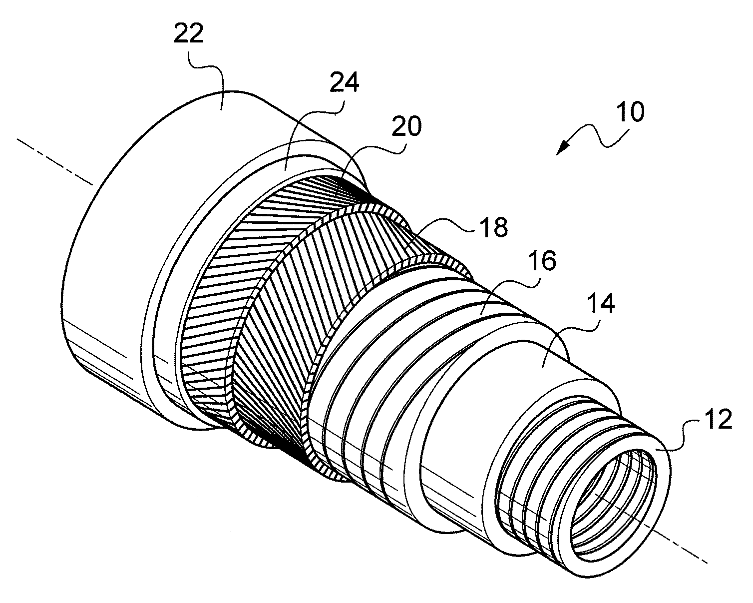
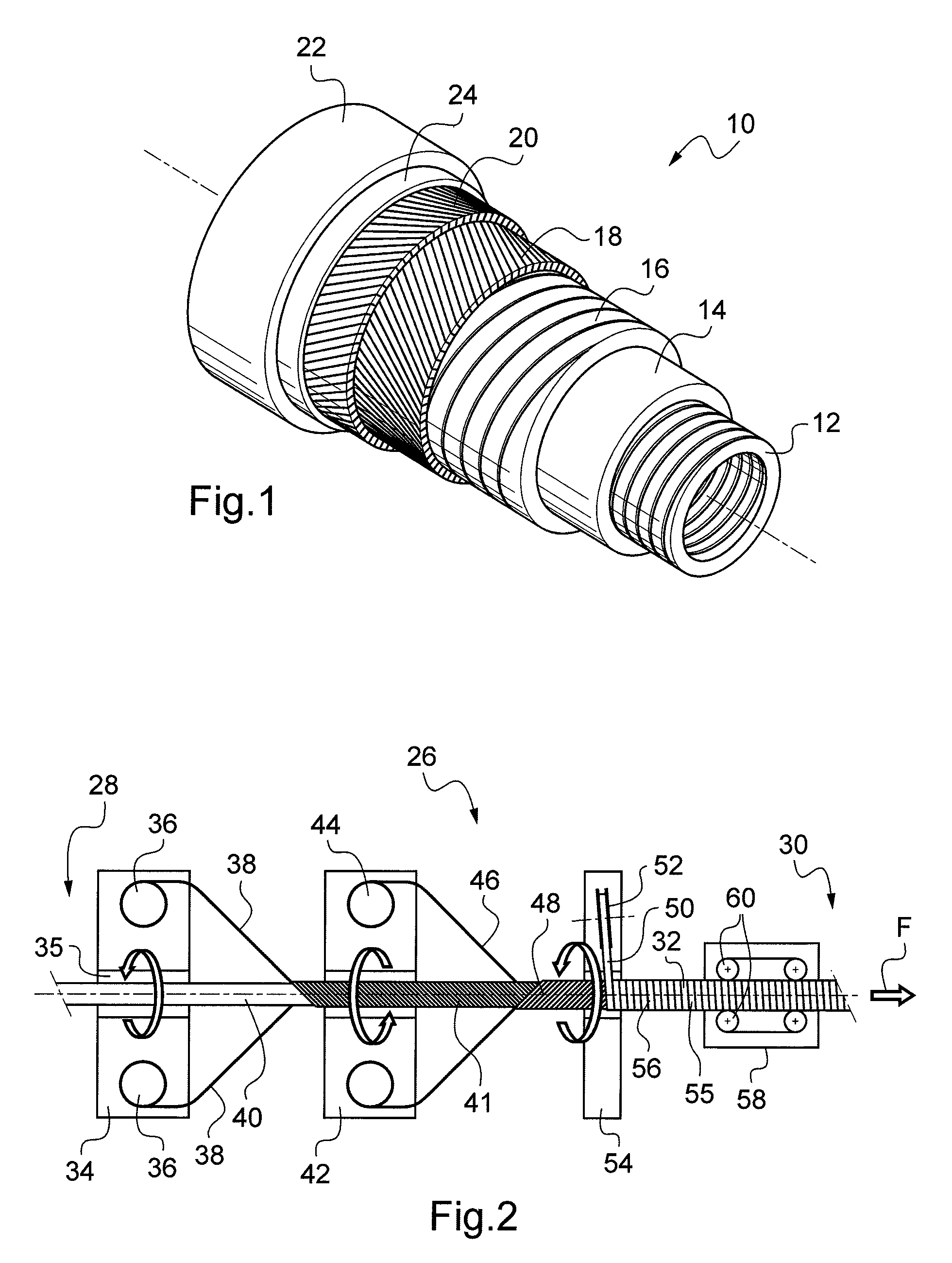

Image

  • Flexible tubular underwater pipe for great depths, and method for manufacturing same
  • Flexible tubular underwater pipe for great depths, and method for manufacturing same
  • Flexible tubular underwater pipe for great depths, and method for manufacturing same

Examples


first embodiment

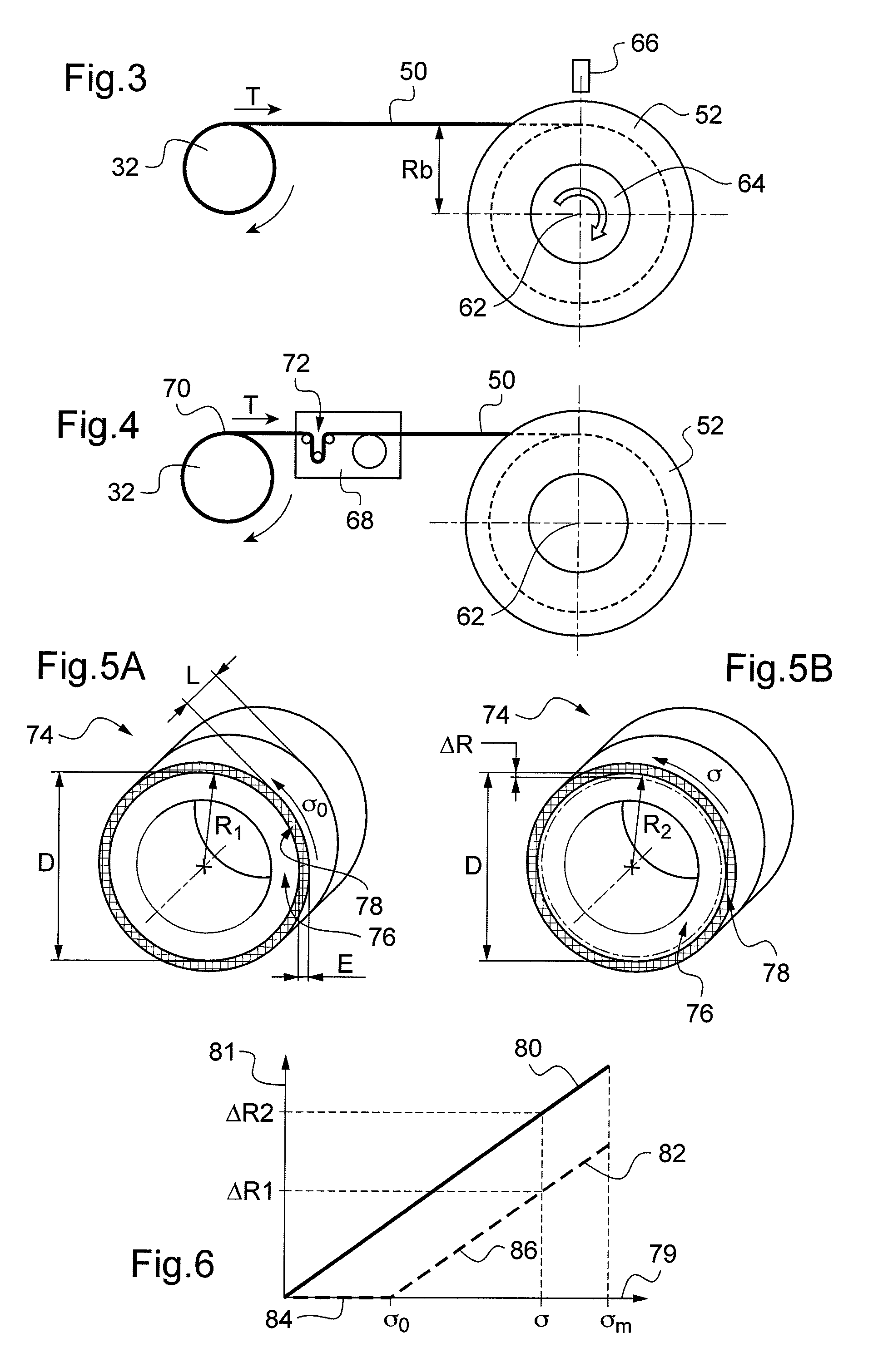
[0045]the spiral winder 54 will now be detailed with reference to FIG. 3, said spiral winder making it possible to apply the anti-inflation strip 50 by imparting on it a tension T.

[0046]As will be explained hereinbelow in more detail, the anti-inflation strip 50 is produced from a deformable synthetic material made of woven fibers, for example aramid fibers. According to the invention, the strip 50 is stretched according to a longitudinal tension T0 so as to stretch said deformable material according to a relative elongation corresponding to a tensile stress σ0 less than the elastic limit value σE of said deformable material, for example to σE is between 5% and 30% of the elastic limit value σE.

[0047]FIG. 3 once again shows the flexible pipe 32 in cross section and the anti-inflation strip 50 stored wound on the strip reel 52. The strip reel 52 has a freely rotating shaft, the direction of which is substantially inclined relative to a direction parallel to the pipe 32 so as to form ...

second embodiment

[0051] illustrated in FIG. 4, again showing the pipe 32, the strip 50 and the reel 52 on which it is wound, the tension T of the strip 50 is kept at a constant value by controlled braking means 68, arranged between the strip reel 52 and the tangential point 70 of placement on the flexible pipe. These controlled braking means 68 may, for example, consist of a capstan equipped with a brake slaved to a tension measurement performed by a three-roller system 72 equipped with a force sensor.

[0052]Reference will now be made to FIG. 4 schematically showing pipe sections provided with an anti-inflation strip, to illustrate the manufacturing method according to the invention.

[0053]FIG. 5A shows a section of flexible tubular pipe 74 having, from inside to outside, a leakproof tubular structure 76 covered with two layers of armor wire and an anti-inflation strip 78. The latter, of inner diameter D and of inner radius R (R=D / 2), has a width L and a thickness E and it is wound in a helix with con...


PUM

PropertyMeasurementUnit
Thicknessaaaaaaaaaa
Angleaaaaaaaaaa
Diameteraaaaaaaaaa

Abstract

A method for manufacturing a flexible tubular underwater pipe (10): A leakproof tubular structure (12, 14, 16) is covered with at least one layer (18, 20) of armor wires. At least one continuous longitudinal element made of a deformable material is wound in a helix with short pitch around the layer (18, 20) of armor wires to form a holding layer 24. The at least one longitudinal element is wound under longitudinal tension T0 so as to stretch its deformable material according to a relative elongation corresponding to a tensile stress σ0 less than the elastic limit value σE of the deformable material, and the elastic limit value σE corresponds to a tensile stress beyond which the deformation of the material is irreversible.

Description

CROSS-REFERENCE TO RELATED APPLICATIONS[0001]The present application is a 35 U.S.C. §§371 national phase conversion of PCT / FR2012 / 050662, filed Mar. 29, 2012, which claims priority of French Patent Application No. 1152609, filed Mar. 29, 2011, the contents of which are incorporated by reference herein. The PCT International Application was published in the French language.BACKGROUND OF THE INVENTION[0002]The present invention relates to a method for manufacturing a flexible tubular underwater pipe for transporting fluids of hydrocarbon or other type, intended for use in particular at great depths. It relates also to a pipe obtained according to the method that is the subject of the invention.[0003]It relates more particularly to the pipes of the unbonded type described notably in the following normative documents published by the API (American Petroleum Institute):[0004]API 17J Specification for Unbonded Flexible Pipe.[0005]API RP 17B Recommended practice for Flexible Pipe.[0006]Als...

Claims


Application Information

Patent Timeline
IPC IPC(8): F16L11/10F16L11/08B29C53/80B29C53/58B29C53/70
CPCF16L11/10B29C53/8016F16L11/08F16L11/083B29C53/70B29C2053/8025B29C53/582
Inventor FELIX-HENRY, ANTOINEESTRIER, PASCAL
Owner TECH FRANCE SA
Learn More