
Serialization and database methods for tubulars and oilfield equipment

a technology of tubulars and oilfield equipment, applied in the field of downhole oil/gas well completion equipment identification, can solve problems such as material fatigue and erosive, corrosion wear of the inner and outer diameters of drill pipes, and deficiencies in performing desirable business functions

Active Publication Date: 2013-06-11
WEATHERFORD TECH HLDG LLC
View PDF32 Cites 11 Cited by
  • Summary
  • Abstract
  • Description
  • Claims
  • Application Information

AI Technical Summary

Benefits of technology

This system enables efficient tracking and management of downhole equipment, improving inventory operations by correlating usage data with identification codes, facilitating accurate billing, inventory forecasting, and optimizing equipment reuse, reducing manual errors and enhancing safety by automating the identification process.

Problems solved by technology

One issue that rental companies encounter involves assessing whether the equipment may be safely and reliably reused or is at the end of its lifespan.
Use and rotation of the drill pipe, for example, in the hole leads to material fatigue and erosive and corrosion wearing of the inner and outer diameters of the drill pipe.
Individual asset identification represents another issue that rental companies confront.
However, prohibitive costs and lack of acceptable serial numbering options limits application of any asset tracking achievable by the rental company utilizing such serialization and results in deficiencies with respect to performing desirable business functions of these companies.
For example, the drill pipe may include attachments incorporating steel stenciled serial numbers, which tend to wear or erode away over time, require manual inspection & replacement, and may need cleaning to be visible.
Attempts to identify drill pipe with radio frequency identification tags affixed to the drill pipe require expensive, complex and / or obtrusive attachment configurations that may harm performance of the drill pipe and often cannot withstand operations downhole.

Method used


Image

  • Serialization and database methods for tubulars and oilfield equipment
  • Serialization and database methods for tubulars and oilfield equipment
  • Serialization and database methods for tubulars and oilfield equipment

Examples


Embodiment Construction

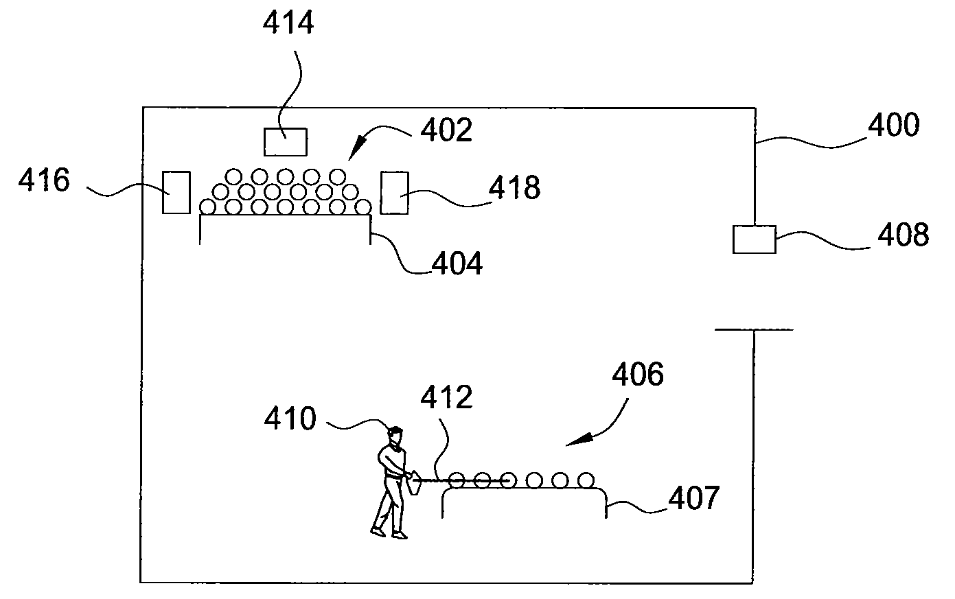
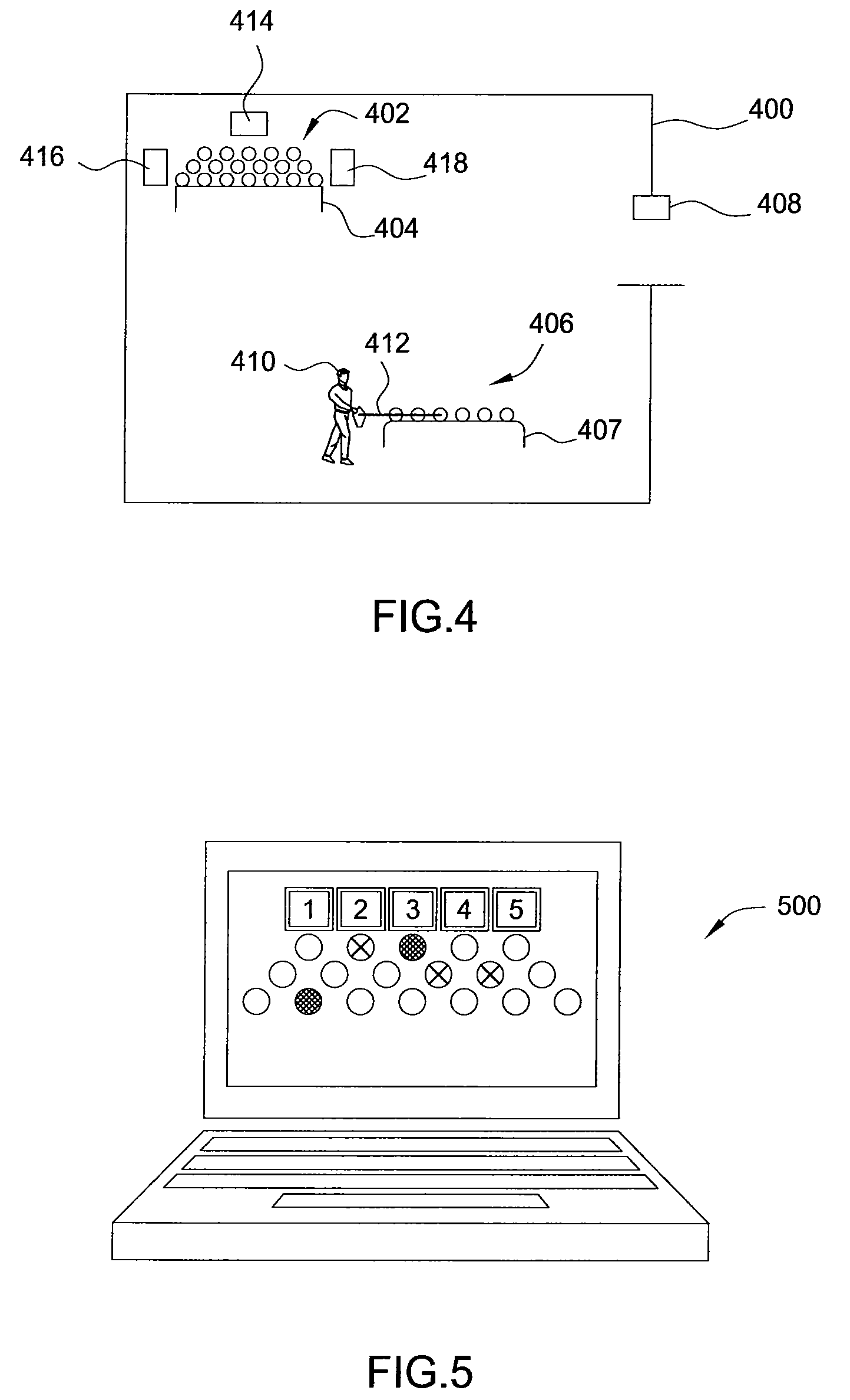
[0026]Embodiments of the invention relate to identification of downhole equipment and correlation of input data with the equipment to improve operations. For some embodiments, oilfield equipment or tubular goods such as drill pipe include an improved tag. Once tagged, detector system configurations at pipe yards may facilitate logging the presence and location of each drill pipe and correlating specific data, such as inspection and usage data, to each drill pipe. Further, this correlation populates a database utilized to achieve other business functions such as forecasting and refining future puchasing of additional drill pipe, handling customers' accounts, returning drill pipe based on actual tracked wear / use of the drill pipe being returned, and providing well or job specific drill string population using known history pipe joints.

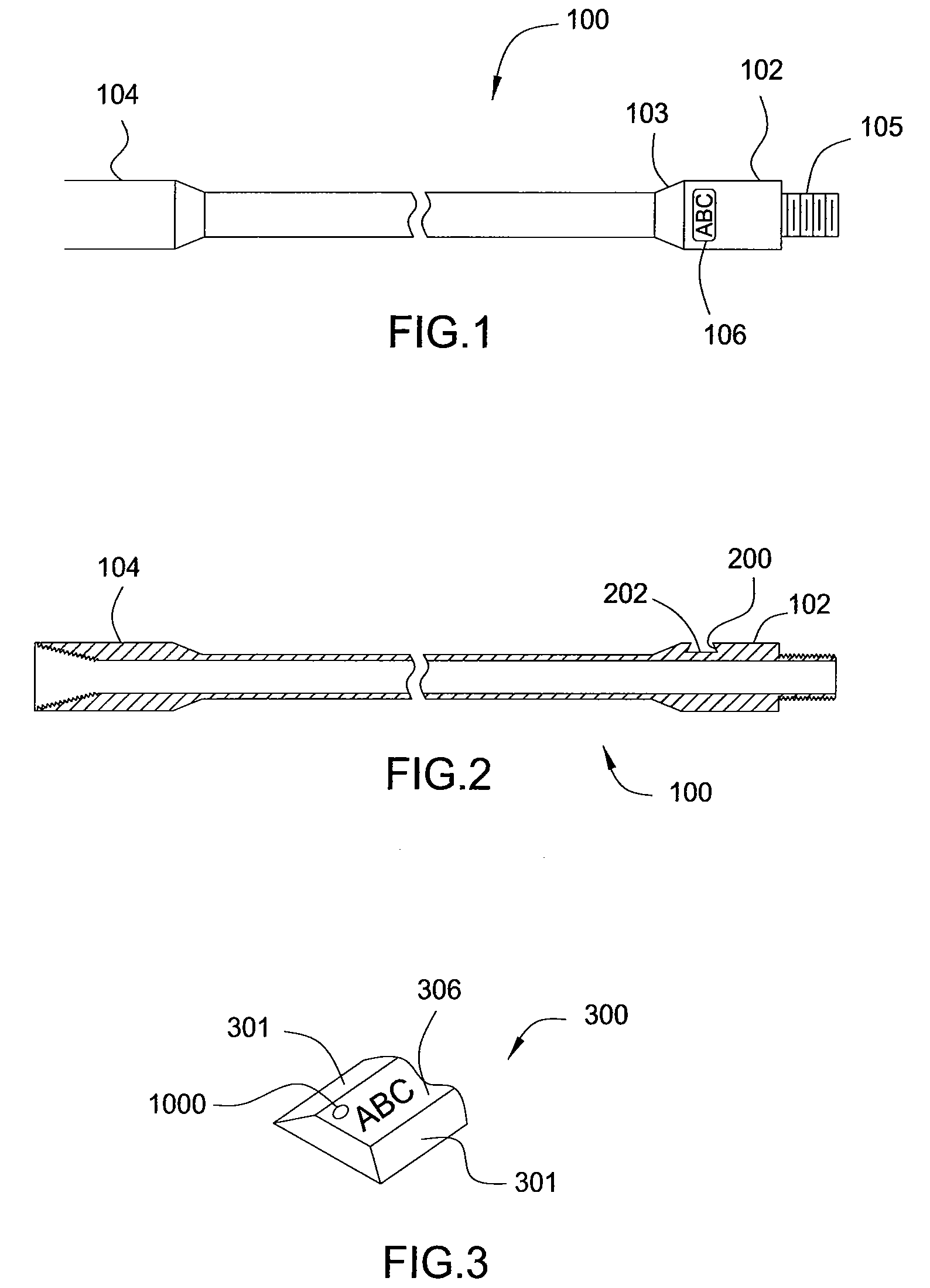
[0027]FIGS. 1 and 2 illustrate a drill pipe 100 having a pin end 102 and a box end 104. The pin end 102 includes an identification groove 106 with sides...


PUM


Abstract

Methods and apparatus identify downhole equipment and correlate input data with the equipment to improve planning and / or inventory operations. For some embodiments, oilfield equipment or tubular goods such as drill pipe include a shaped recess along an outer circumference for receiving a tag cartridge by shrink fitting. Once tagged, detector system configurations at pipe yards may facilitate logging the presence and location of each drill pipe and correlating specific data, such as inspection data, to each drill pipe. Further, this correlation populates a database utilized to achieve other business functions such as forecasting number of additional drill pipe needed to purchase, invoicing customers according to actual tracked wear / use of the drill pipe being returned, and providing well or job specific drill string population using known history pipe joints.

Description

CROSS-REFERENCE TO RELATED APPLICATIONS[0001]This application claims benefit of U.S. provisional patent application Ser. No. 60 / 740,406, filed Nov. 28, 2005, which is herein incorporated by reference.BACKGROUND OF THE INVENTION[0002]1. Field of the Invention[0003]Embodiments of the invention generally relate to identification of downhole oil / gas well drilling and completion equipment and correlation of input data with the equipment to improve inventory and planning operations.[0004]2. Description of the Related Art[0005]Exploration, production and completion of hydrocarbon wells require numerous pieces of oilfield or downhole equipment, such as mud motors, drill bits, underreamers, jars, drill collars, measurement-while-drilling (MWD) or logging-while-drilling (LWD) tools, cementing plugs or floats, and other tubular goods including drill pipe, casing and expandable casing, liners and expandable liners, and sand screens. Much of this equipment lasts for many years of usage such that...

Claims


Application Information

Patent Timeline
Patent Type & Authority Patents(United States)
IPC IPC(8): G06Q10/00G06Q20/20
CPCE21B17/006G06Q10/087G06Q20/203E21B19/00
Inventor GRIGGS, PAUL STEVENLJUNGDAHL, PATRICK M.SARRADET, STEPHENWILLIAMS, LARRYMILLER, MATTHEW G.HARRALL, SIMON JOHNLE, TUONG THANH
Owner WEATHERFORD TECH HLDG LLC
Learn More