
Solar combiner with integrated string current monitoring

a solar combiner and current monitoring technology, applied in the field of solar combiners, can solve the problems of damage to the wiring panel, adversely affecting the performance of the pv array, and individual strings connected to the combiners to underperform

Active Publication Date: 2013-06-18
SCHNEIDER ELECTRIC USA INC
View PDF11 Cites 9 Cited by
  • Summary
  • Abstract
  • Description
  • Claims
  • Application Information

AI Technical Summary

Benefits of technology

The patent describes a solar combiner that can track the energy production of each individual string of solar panels without needing any current transformers, modifications to the panels or inverter, or adding complexity to existing equipment. This makes it easier to monitor and manage the performance of solar arrays.

Problems solved by technology

Backfeeding current into a PV panel can damage the wiring panel or otherwise adversely affect the performance of the PV array.
Individual strings connected to the combiner can underperform for one of several reasons, including the presence of a ground fault in the string, a loose wire in the string, solar tracking of the PV panel is misadjusted, and so forth.
Conventional software in the DC-to-AC inverter can indicate a drop in performance of the PV array as a whole, but the inverter has no way of knowing which PV array is underperforming or has a problem let alone which individual string is underperforming or has a problem.
To troubleshoot which individual string might be the source of the problem involves manual labor and extensive troubleshooting of the entire array until the source of the problem is found.
If an underperforming or troublesome string goes unnoticed, is ignored, or is undetected, a substantial decrease in power generation and a loss of revenue can occur.
More seriously, if the problem is caused by a loose wire connection or a ground fault, a hazardous condition can persist creating a potentially dangerous condition depending on the installation of the string, such as on a building or in other areas where humans can be present.

Method used


Image

  • Solar combiner with integrated string current monitoring
  • Solar combiner with integrated string current monitoring
  • Solar combiner with integrated string current monitoring

Examples


Embodiment Construction

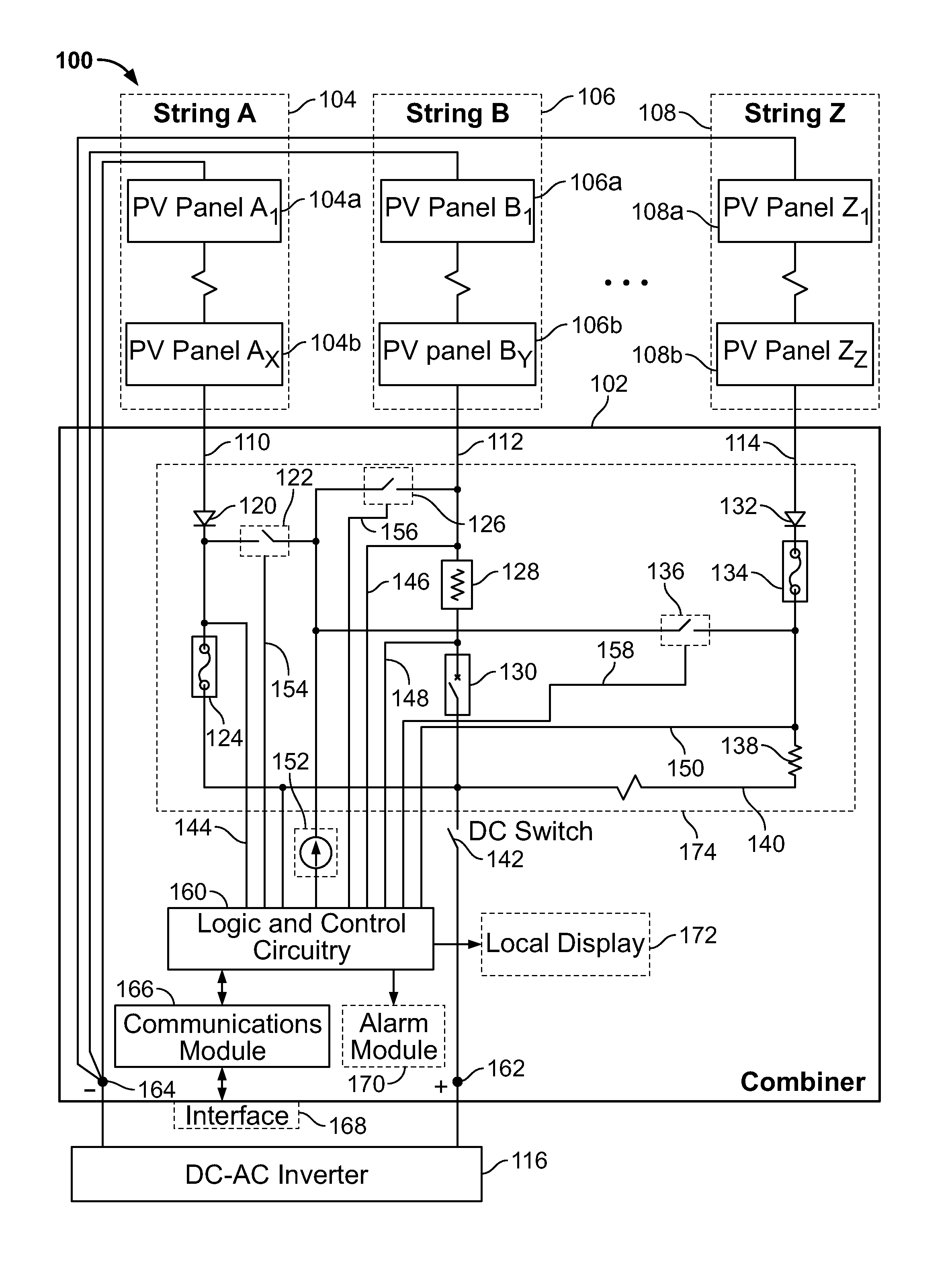
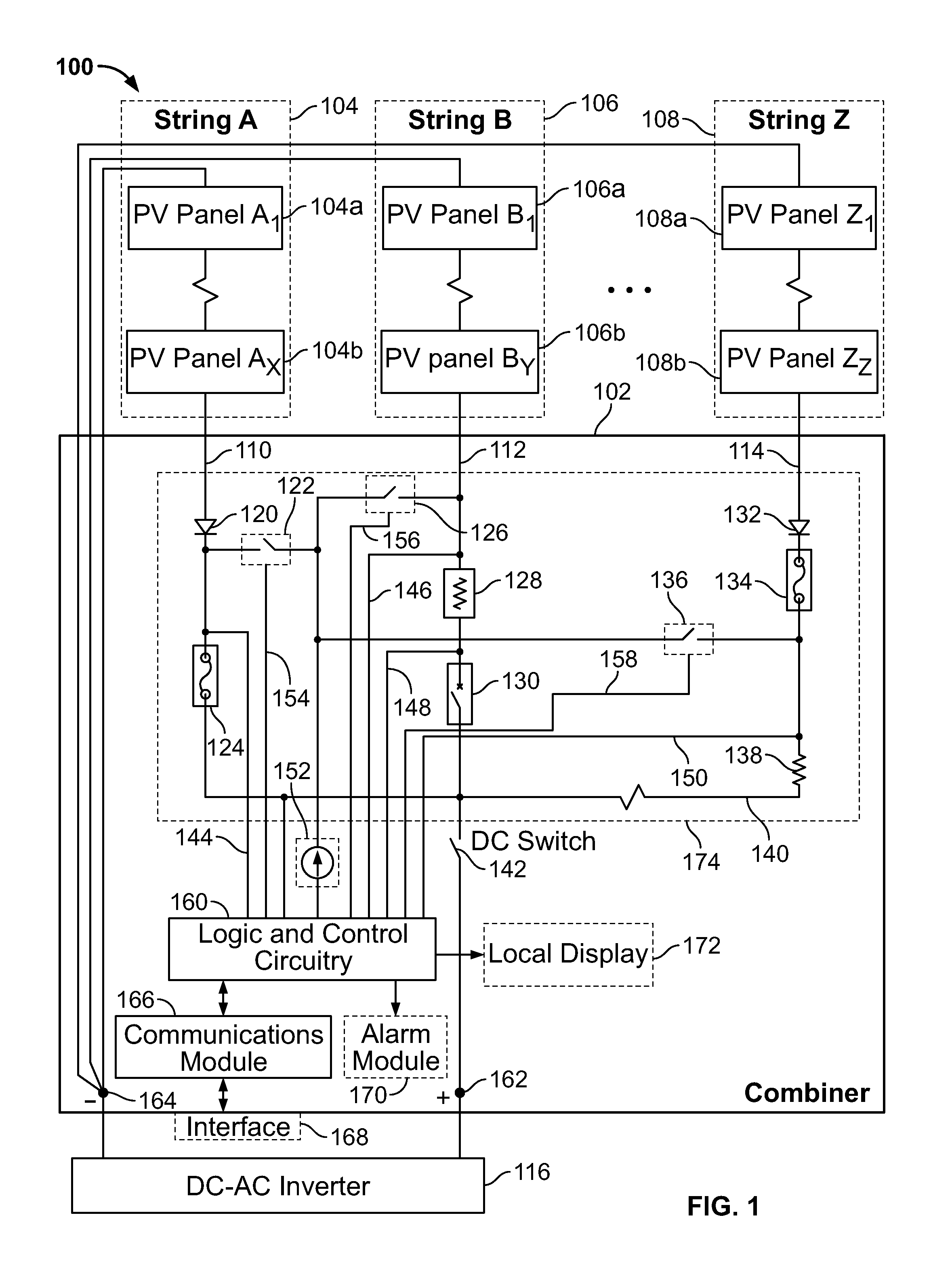
[0016]FIG. 1 is a functional block diagram of a photovoltaic (PV) array system or apparatus assembly 100 that includes strings (A, B . . . Z) 104, 106, 108 of series-connected PV panels (A1 . . . Ax, B1 . . . By, Z1 . . . Zz) 104a, 104b, 106a, 106b, 108a, 108b that are connected to a corresponding panel feed 110, 112, 114 in a first-level combiner box 102. Each PV panel conventionally includes an array of PV cells, which convert solar or other light energy into a corresponding DC current, which can be stored in a battery or other storage device and / or used to power DC or AC electrical loads. The combiner box 102 has an enclosure, such as a metal housing, that houses and protects components within the combiner box 102, such as against physical intrusion and environmental pollution. A combiner, in the context of the present disclosure, receives individual feeds of DC current from strings of PV panels and “combines” each of those DC currents onto a single conductor 140, typically calle...


PUM


Abstract

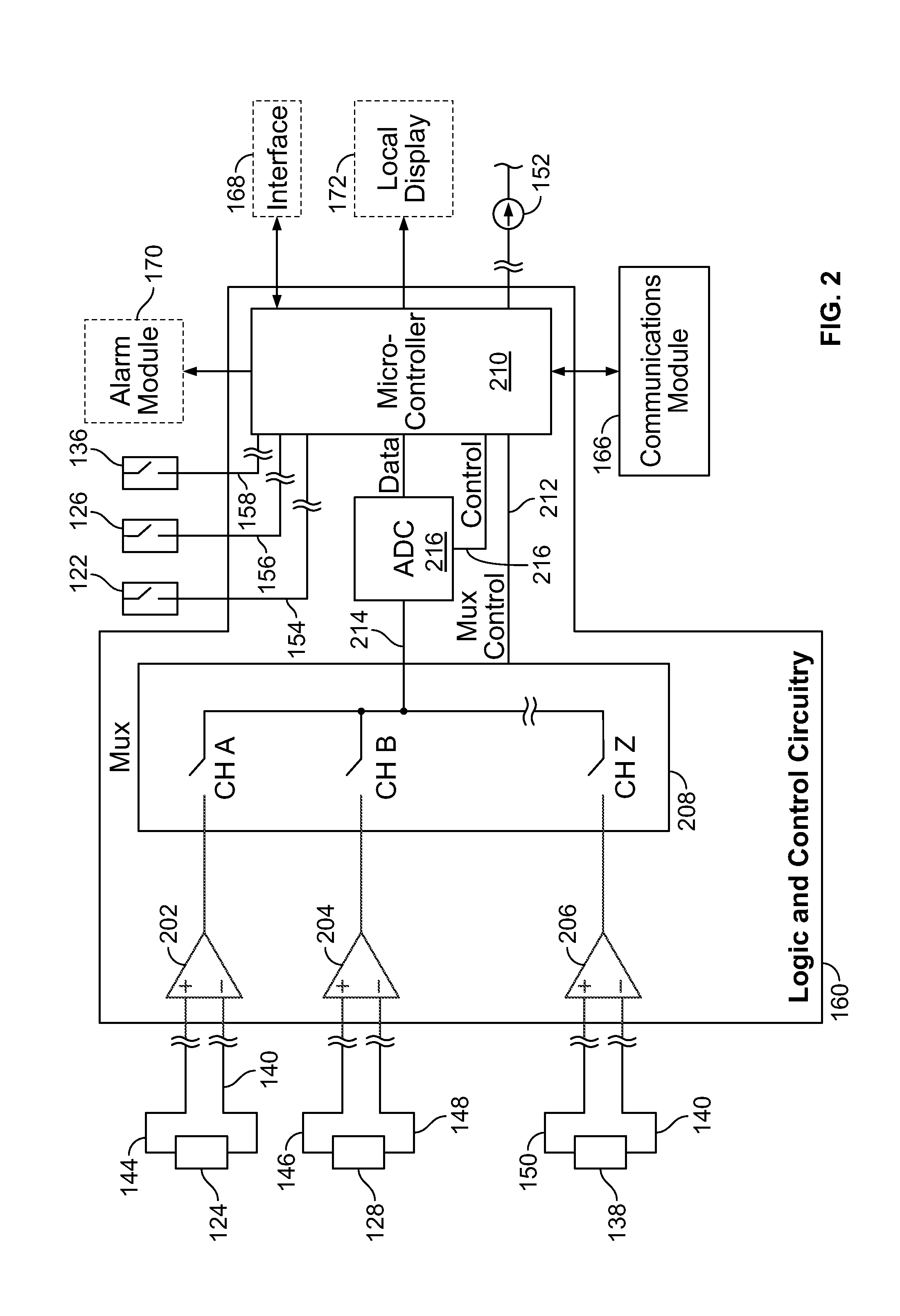
A combiner that calculates energy produced by each panel feed during the daytime, and calculates a resistance value needed to calculate the energy by injecting a known current into each panel feed at nighttime and measuring the resulting voltage across a resistive element in each panel feed. A voltage tap across the protection device in each panel feed allows logic and control circuitry to measure the voltage across each protection device. At nighttime, a known current is injected into each panel feed and the voltage across each protection device is measured. Plugging the current and voltage into Ohm's Law, a resistance of each protection device is calculated, then that resistance value is used during the daytime to calculate energy produced by each string in real time and to monitor each string's performance. When an individual string's performance wanes, an alarm is indicated to help the operator troubleshoot which individual panel(s) within the string is responsible for that string's underperformance.

Description

FIELD OF THE INVENTION[0001]Aspects of the present disclosure relate generally to solar combiners, and, more particularly, to solar combiners with integrated current monitoring on an individual string basis.BACKGROUND[0002]A solar photovoltaic (PV) array is a parallel arrangement of strings of series-connected PV panels. A string in the context of PV arrays is an arrangement of PV panels connected together in series. A PV array is composed of multiple strings of PV panels. Each string output is received in a device called a combiner, which “combines” the current from each string into a larger conductor, called a busbar, for feeding downstream equipment such as disconnect switches, possibly other lower-level combiners, and ultimately to a DC-to-AC inverter that converts the DC currents produced by each string of the PV array into a corresponding AC current. The combiner can receive strings from one or more PV arrays.[0003]In the combiner, which typically takes the form of an enclosur...

Claims


Application Information

Patent Timeline
Patent Type & Authority Patents(United States)
IPC IPC(8): G01R31/26
CPCH02J13/00
Inventor RAMSEY, JAMES RAYMONDSHARP, JEFFREY OWEN
Owner SCHNEIDER ELECTRIC USA INC
Learn More