System for converting at least one electrical input direct current into an electrical polyphase output alternating current

a technology of electrical polyphase and alternating current, which is applied in the direction of dc-ac conversion without reversal, process and machine control, instruments, etc., can solve the problems of relatively large line voltage drop in conversion systems of this type, and the conversion system of this type is not modular, so as to reduce the generated line voltage drop and the effect of adding an inverter

Active Publication Date: 2013-06-18
CONVERTEAM TECH LTD
View PDF15 Cites 1 Cited by
  • Summary
  • Abstract
  • Description
  • Claims
  • Application Information

AI Technical Summary

Benefits of technology

[0013]An object of the present invention is to propose a modular conversion system, in order to make it easier to add an inverter in parallel, and making it possible to obtain a lower common mode inductance between the phases of the various inverters, in order to reduce the generated line voltage drops.
[0016]Combination of the first and second electromagnetic coupling coils for each phase of the output current thus makes it possible to reduce the common mode current between the different phases of the output current. In fact, the common mode fluxes generated respectively by the first coil and second coil of a single core are in phase and of opposite directions, so that they cancel each other out partially. The line voltage drops in common mode are thus greatly reduced. Additionally, this reduction of the line voltage drops is obtained without increasing the inductance, and thus overall dimensions, of the first and second coupling coils.
[0017]The magnetic components of the conversion system according to the invention make it possible to obtain, simultaneously, low common mode inductance (low voltage drop) and high differential mode inductance (inductance limiting the circulating currents).
[0018]Comparison with a conventional conversion system, for the same number of turns, same size of conductors and same cross-section of each core, shows that the conversion system according to the invention makes it possible to reduce the generated line voltage drops.
[0027]Adding a return magnetic column to each magnetic coupler makes it possible to reduce the homopolar current for each phase of the output current. This is achievable both in the case of a single input bus which is common to all the inverters, and in the case of a distinct input bus for each inverter. However, in the case of a distinct input bus for each inverter, it will be more advantageous, for reasons of cost and overall dimensions, to connect a line resistor of high value between the capacitive mid-point of each bus and the electrical earth.
[0028]The magnetic components of the conversion system according to the invention thus make it possible to obtain a homopolar inductance (impedance) of high value, to reduce the homopolar mode currents.

Problems solved by technology

However, conversion systems of this type are not modular, since adding an inverter, in parallel with the other inverters which are already present, makes it necessary to add a magnetic core equipped with a coupling coil in each magnetic coupler.
Also, conversion systems of this type generate relatively large line voltage drops.

Method used


Image

  • System for converting at least one electrical input direct current into an electrical polyphase output alternating current
  • System for converting at least one electrical input direct current into an electrical polyphase output alternating current
  • System for converting at least one electrical input direct current into an electrical polyphase output alternating current

Examples


Embodiment Construction

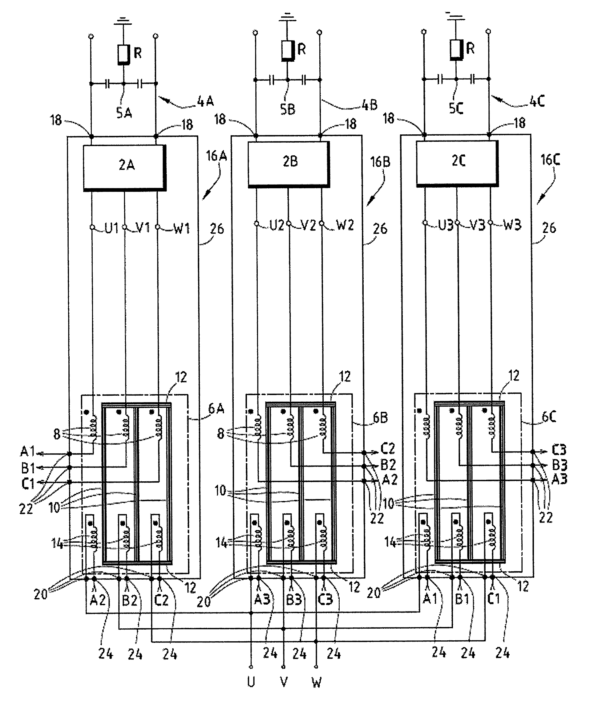
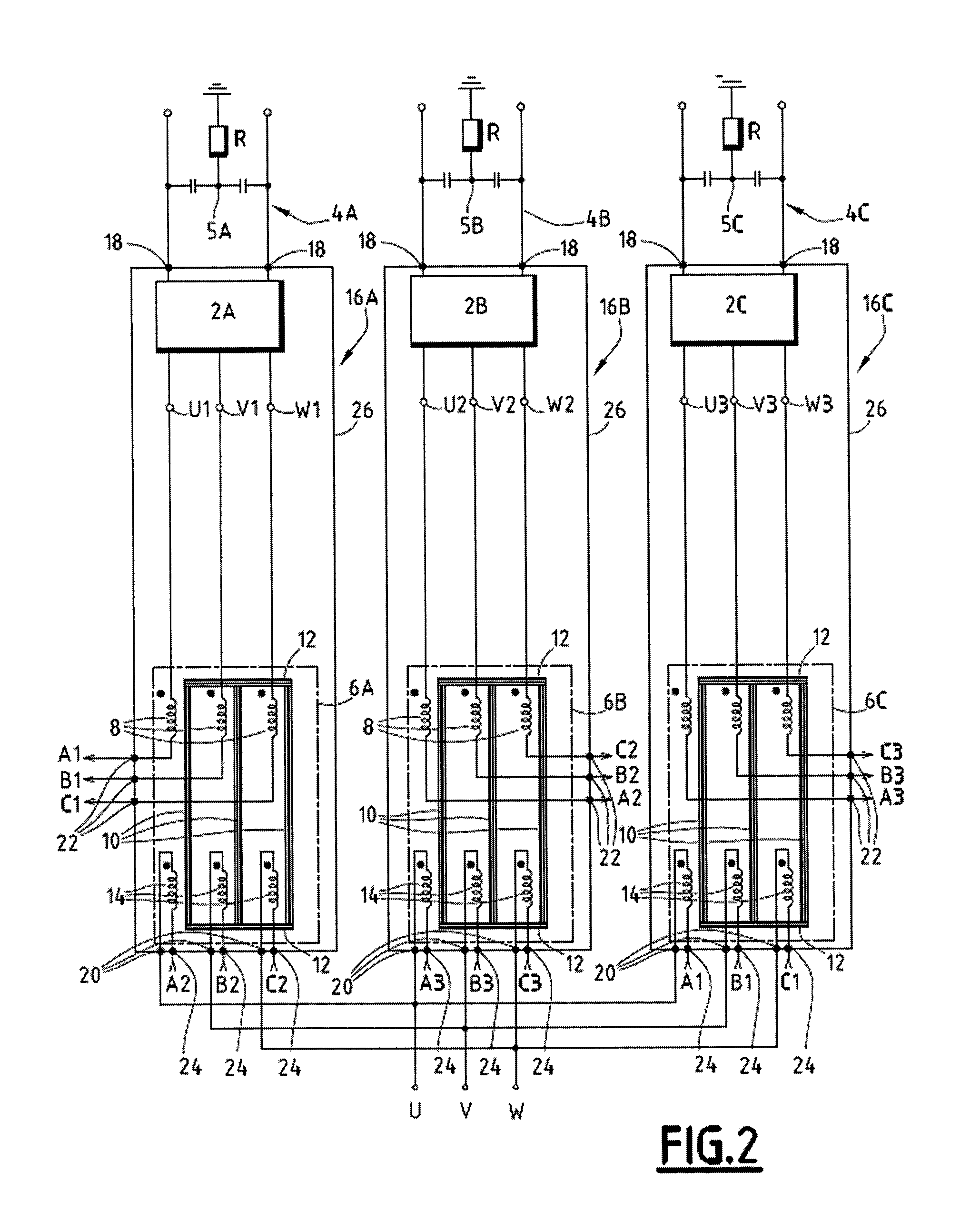
[0051]It should be remembered that, in the rest of the description, two points marked by the same letter in a figure are, by convention, connected to each other by an electrical link, which is not shown to make the diagram easier to read.

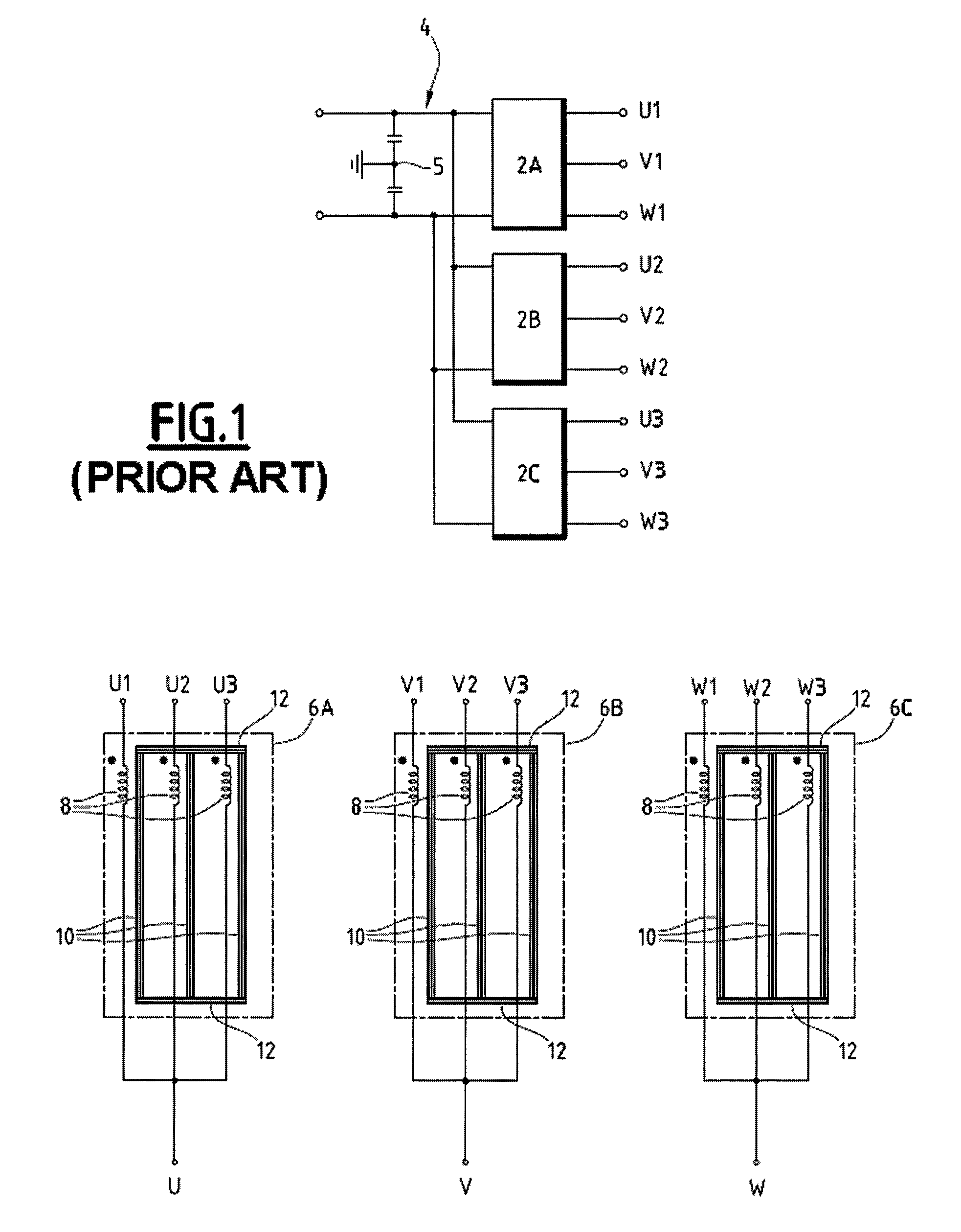
[0052]Referring to FIG. 2, it can be seen that the conversion system of the invention comprises, firstly, the same components as those of FIG. 1, i.e. three three-phase inverters 2A, 2B, 2C arranged in parallel with each other, and three magnetic couplers 6A, 6B, 6C each including three first electromagnetic coupling coils 8. Each first electromagnetic coupling coil 8 is wound around a respective core 10, the cores 10 of a single magnetic coupler 6A, 6B, 6C being connected to each other by magnetic linking bars 12.

[0053]In the embodiment of FIG. 2, the cores 10 and magnetic linking bars 12 of a same magnetic coupler 6A, 6B, 6C are approximately coplanar. The cores 10 are approximately parallel to each other, and the magnetic linking bars 12 are appr...


PUM


Abstract

A system for converting at least one electrical input direct current into an electrical output alternating current comprising M phases and supplied to M output terminals includes N polyphase inverters, connected in parallel, each converting the input direct current into an intermediate alternating current comprising M phases and supplied to M intermediate terminals; N×M first electromagnetic coupling coils, each being connected to a respective intermediate terminal; N×M magnetic cores, each first coil being wound around a respective core.This system comprises N×M second electromagnetic coupling coils, each being connected to a respective first coil and wound around a distinct core from that of the respective first coil. The first and second coils of a same core correspond to a single phase, and generate respective common mode fluxes of opposite directions. Each output terminal is connected to the M second coils of a single phase.

Description

[0001]This claims the benefit of French Patent Application No. 08 59062, filed on Dec. 24, 2008 and hereby incorporated by reference herein.[0002]The present invention relates to a system for converting at least one electrical input direct current into an electrical output alternating current comprising a plurality M of phases and supplied to M output terminals, each output terminal corresponding to one phase of the output current.[0003]The invention also relates to a module for converting an electrical input direct current which is supplied at two input terminals into an electrical output alternating current comprising a plurality M of phases and supplied to M output terminals, each output terminal corresponding to one phase of the output current.[0004]The invention also relates to a conversion system, which is equipped with multiple conversion modules connected in parallel with each other.[0005]The invention also relates to electrical power equipment which is equipped with at leas...

Claims


Application Information

Patent Timeline
Patent Type & Authority Patents(United States)
IPC IPC(8): H02M7/538H02M7/5383
CPCH02M7/493
Inventor COSTAN, VALENTINGOLLENTZ, BERNARD
Owner CONVERTEAM TECH LTD
Why Eureka
Try Eureka