Method and machine for separating liquid crystal panel and liner pad

a liquid crystal panel and liner pad technology, applied in the direction of controlling lamination, other domestic objects, chemistry apparatus and processes, etc., can solve the problems of air contained in the recessed channels of the liner pad to be expelled, trouble for the subsequent module process and customers, etc., to shorten the time period required for separation, reduce manufacturing costs, and efficiently separate the stuck

Active Publication Date: 2013-06-25
TCL CHINA STAR OPTOELECTRONICS TECH CO LTD
View PDF8 Cites 34 Cited by
  • Summary
  • Abstract
  • Description
  • Claims
  • Application Information

AI Technical Summary

Benefits of technology

[0006]An object of the present invention is to provide a method for separating a liquid crystal panel and a liner pad, which efficiently separates the stuck liquid crystal panel and liner pad without causing damage to the liquid crystal panel during the separation process and shortens the time period required for the separation thereby lowering the manufacture cost.

Problems solved by technology

The liner pad, which is subjected to a pressing force of the liquid crystal panel, may undergo deformation, causing air contained in recessed channels of the liner pad to be expelled out and the liner pad sticking to the liquid crystal panel.
The combination of the liquid crystal panel and the liner pad so formed is hard to break up, causing troubles to the subsequent module process and customers.

Method used


Image

  • Method and machine for separating liquid crystal panel and liner pad
  • Method and machine for separating liquid crystal panel and liner pad
  • Method and machine for separating liquid crystal panel and liner pad

Examples


Embodiment Construction

[0030]To further expound the technical solution adopted in the present invention and the advantages thereof, a detailed description is given to a preferred embodiment of the present invention and the attached drawings.

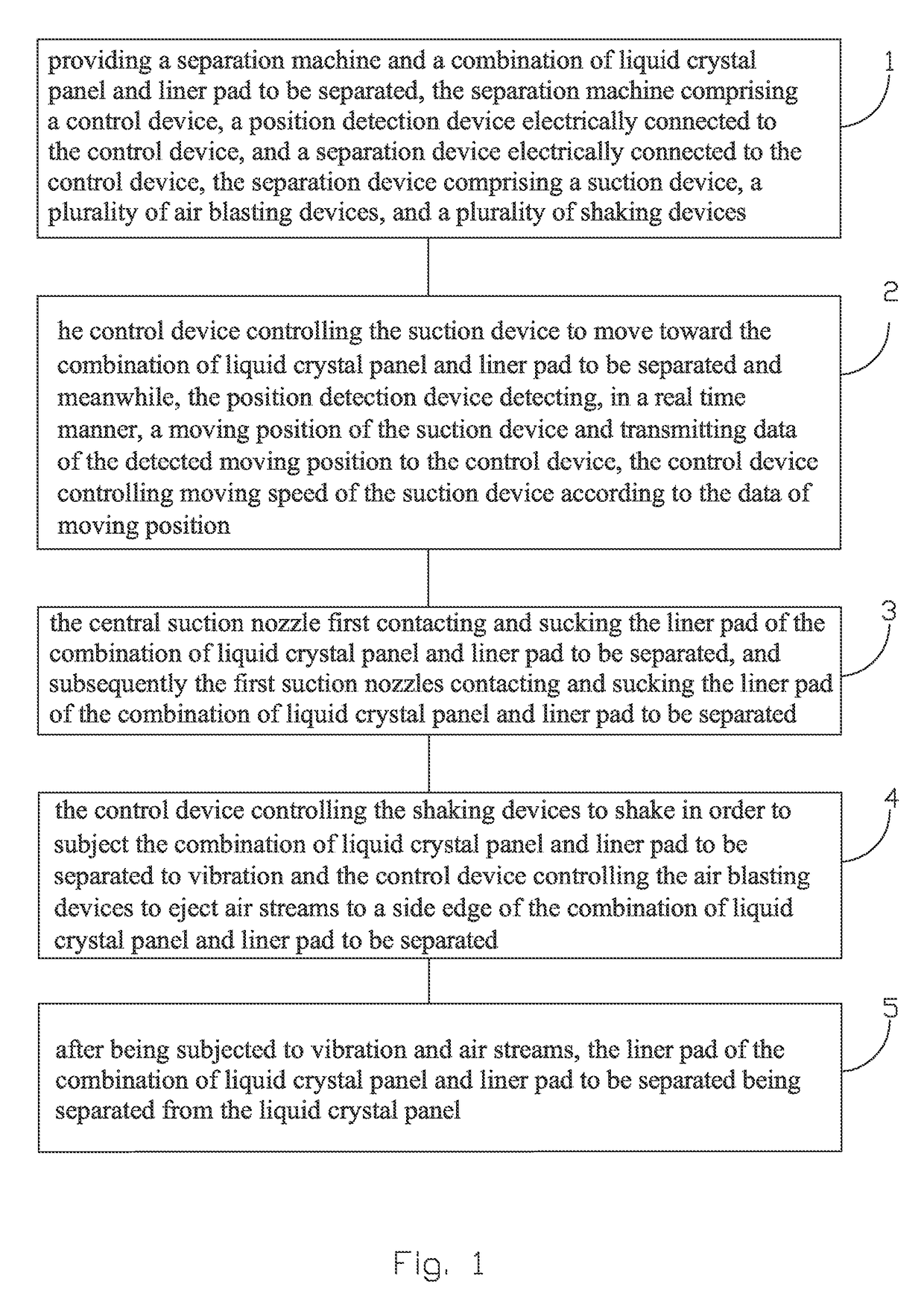
[0031]Referring to FIG. 1, the present invention provides a method for separating a liquid crystal panel and a liner pad, which comprises the following steps:

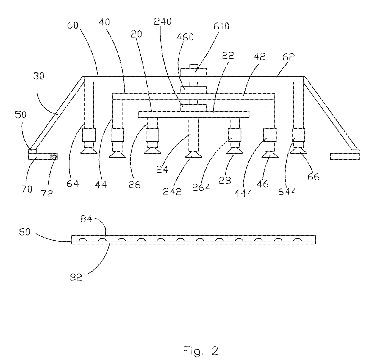
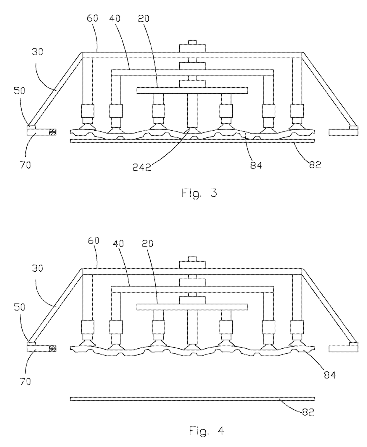
[0032]Step 1: providing a separation machine and a combination of the liquid crystal panel and liner pad to be separated, the separation machine comprising a control device, a position detection device electrically connected to the control device, and a separation device electrically connected to the control device, the separation device comprising a suction device, a plurality of air blasting devices, and a plurality of shaking devices, the suction device comprising a first suction unit, the first suction unit comprising a first connection bar, a central suction arm mounted to a center of the first connection bar...


PUM

PropertyMeasurementUnit
sizeaaaaaaaaaa
sizeaaaaaaaaaa
sizeaaaaaaaaaa

Abstract

The present invention provides a method and machine for separating a liquid crystal panel and a liner pad. The method includes (1) providing a separation machine and a combination of the liquid crystal panel and liner pad to be separated, the separation machine including a separation device that includes a suction device, air blasting devices and shaking devices; (2) the suction device moving toward the combination; (3) a central suction nozzle first engaging and sucking a liner pad of the combination and later the first suction nozzles engaging the sucking the liner pad of the combination; (4) the shaking devices being operated to subject the combination to vibration and the air blasting devices being operated to eject air streams to side edges of the combination; and (5) the combination, after being subjected to vibration and air streams, being separated so as to realize separation of the liquid crystal panel and liner pad.

Description

BACKGROUND OF THE INVENTION[0001]1. Field of the Invention[0002]The present invention relates to the field of manufacture of liquid crystal displays, and in particular to a method and machine for separating a liquid crystal panel and a liner pad.[0003]2. The Related Arts[0004]The progress of modern technology brings new displaying techniques. Considering the large scale of mass production, the liquid crystal display devices are now the main stream of flat display devices. Recently, most of the mobile phones, notebook computers, and digital cameras adopt a liquid crystal display device as a display screen thereof.[0005]In the current TFT-LCD (Thin-Film Transistor Liquid Crystal Display) industry, after being manufactured, liquid crystal panels are subjected to inspection and classification according to quality thereof. Afterwards, the liquid crystal panels and liner pads are sequentially positioned in a package box in a spaced manner. With the generation of panel getting higher and h...

Claims


Application Information

Patent Timeline
Patent Type & Authority Patents(United States)
IPC IPC(8): B32B38/10
CPCB32B38/10H01L21/67092H01L21/6838B32B41/00Y10T156/1944B32B2309/68B32B2310/0454B32B2457/202Y10T156/1922Y10T156/1137Y10T156/1168Y10T156/1939Y10T156/1132Y10T156/1121Y10T156/1978
Inventor WANG, XINGANG
Owner TCL CHINA STAR OPTOELECTRONICS TECH CO LTD
Why Eureka
Try Eureka