
Double break vacuum interrupter

a vacuum interrupter and double break technology, applied in the direction of air break switches, high-tension/heavy-dress switches, electrical appliances, etc., can solve the problems of long arcing time, complex and costly operating mechanisms, bulky switchgear units, etc., and achieve the effect of interruption

Inactive Publication Date: 2013-06-25
GLASER MICHAEL DAVID
View PDF32 Cites 19 Cited by
  • Summary
  • Abstract
  • Description
  • Claims
  • Application Information

AI Technical Summary

Benefits of technology

This patent text describes a mechanism that allows for adjusting the tolerance accumulation of components, positioning a floating contact, and controlling its range of motion. This mechanism can be used to align the primary and secondary contact systems. This invention can also provide a coaxial magnetic field and cancellation of magnetic fields outside the contact structure. The technical effects of this patent text include improved interruption effectiveness and stability of the arc at the outside contact ring, as well as the reduction of plasma expulsion from the interruption.

Problems solved by technology

The first three cited patents present devices in which two moving contact structures must be moved in opposite directs to achieve two series contact breaks, necessitating a complex and costly operating mechanism.
This can result in longer arcing times as the moving contact is drawn through its stroke to establish the multiple breaks as well as severe erosion along the edges of the contacts at the arc transfer points.
This practice requires the use of complex and costly interconnecting mechanisms for the series interrupter modules and results in a bulky switchgear unit.
This configuration is suitable for providing a means to ground the electric circuit in which the vacuum switch or interrupter is employed, but because the contact means is not capable of engaging both sets of contacts by moving in one direction, the device does not provide a double break mechanism.
While work hardening will result in the return of some of the spring force characteristics, its final force characteristics will be uncontrolled.
Additionally, no means is provided to precisely position the driven contact, adjust out the tolerance accumulation between the multiple parts or to balance the voltage between the two contact gaps.
The first cited patent shows an extremely complex method of assuring that the contacts make and break at the same time.
However, U.S. Pat. No. 3,283,101 does not indicate the use of capacitance to balance the voltages between the two contact gaps.
In addition, the fact that the contact structures are mounted in a parallel configuration results in a bulky vacuum module.
The spring would regain some of its spring force with work hardening; however its final force characteristics would be uncontrolled.

Method used


Image

  • Double break vacuum interrupter
  • Double break vacuum interrupter
  • Double break vacuum interrupter

Examples


Embodiment Construction

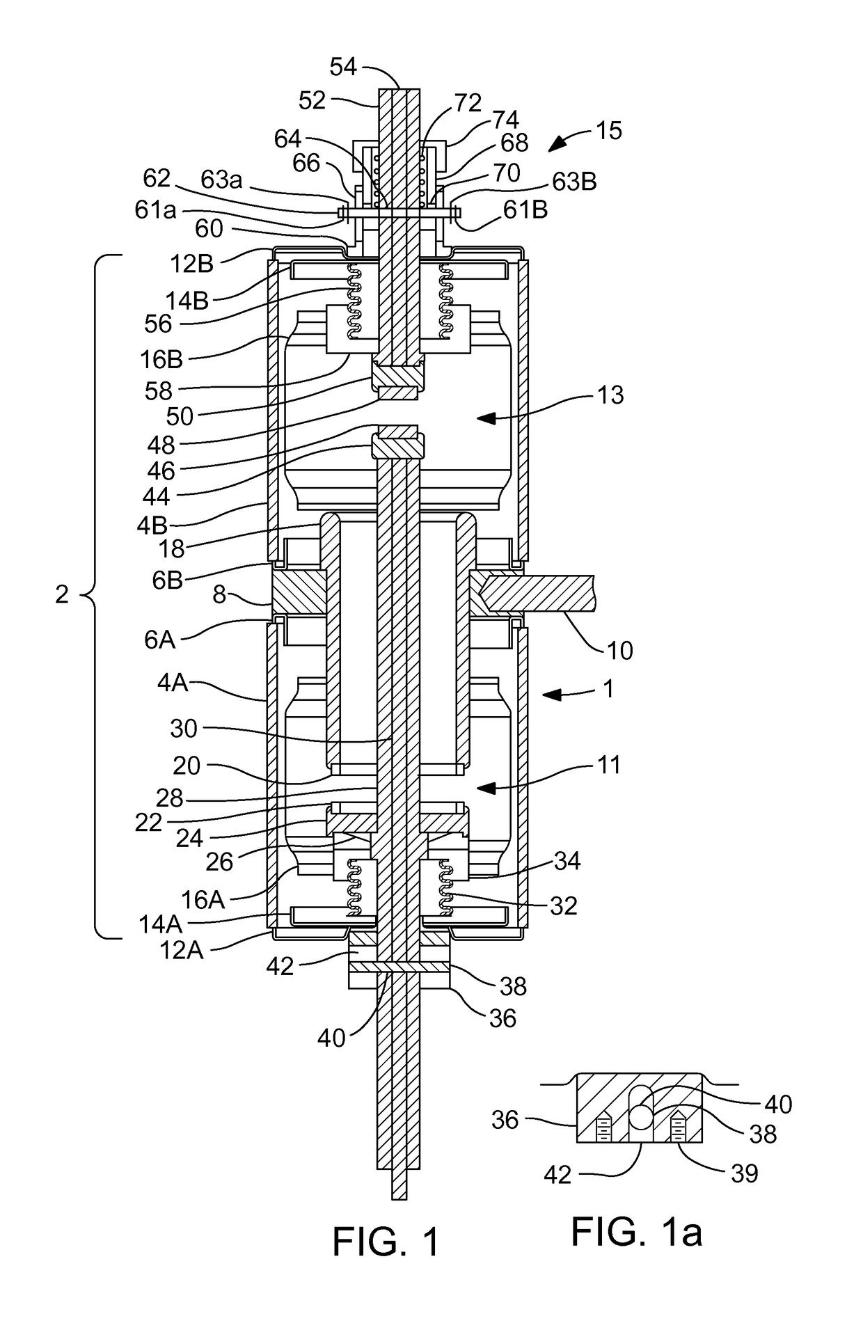
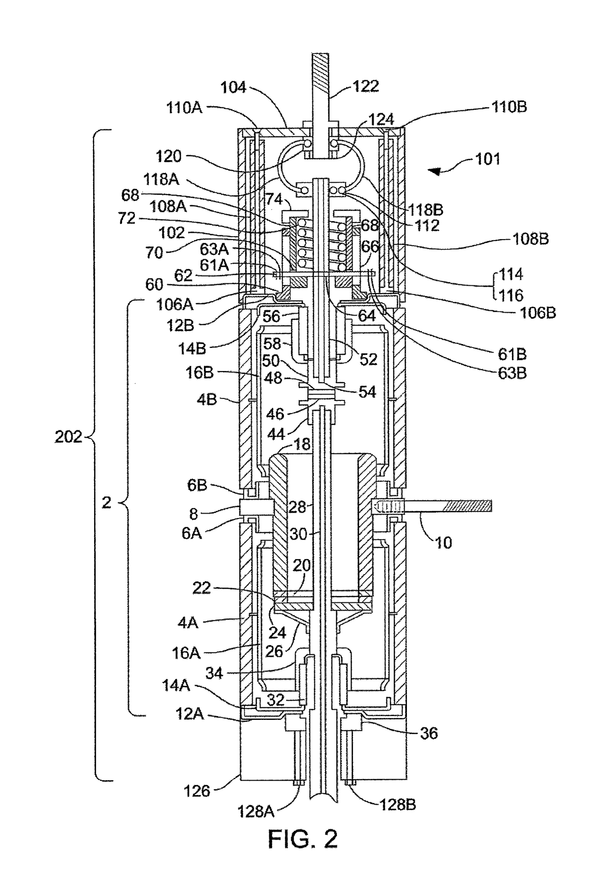
[0026]FIG. 1 discloses a double break vacuum switch (vacuum switch) 1. The vacuum switch 1 includes a vacuum envelope 2. The major part of the vacuum envelope 2 includes a pair of insulating cylinders 4A and 4B preferably fabricated from alumina ceramic joined end-to-end by way of two stainless steel or monel triple point shields 6A and 6B and a stationary contact support ring 8, preferably fabricated from copper. A threaded hole in the stationary contact support ring 8 allows the attachment of a terminal rod 10 to facilitate electrical connection to a source line. Opposite ends of the ceramic cylinders are enclosed by two end cups 12A and 12B, preferably fabricated from stainless steel or monel. A second set of triple point shields 14A and 14B preferably fabricated from stainless steel or monel are attached to the end cups. A generally tubular internal shield 16A and 16B is provided within each insulating cylinder 4A and 4B spaced from the interior wall and overlapping the triple p...


PUM


Abstract

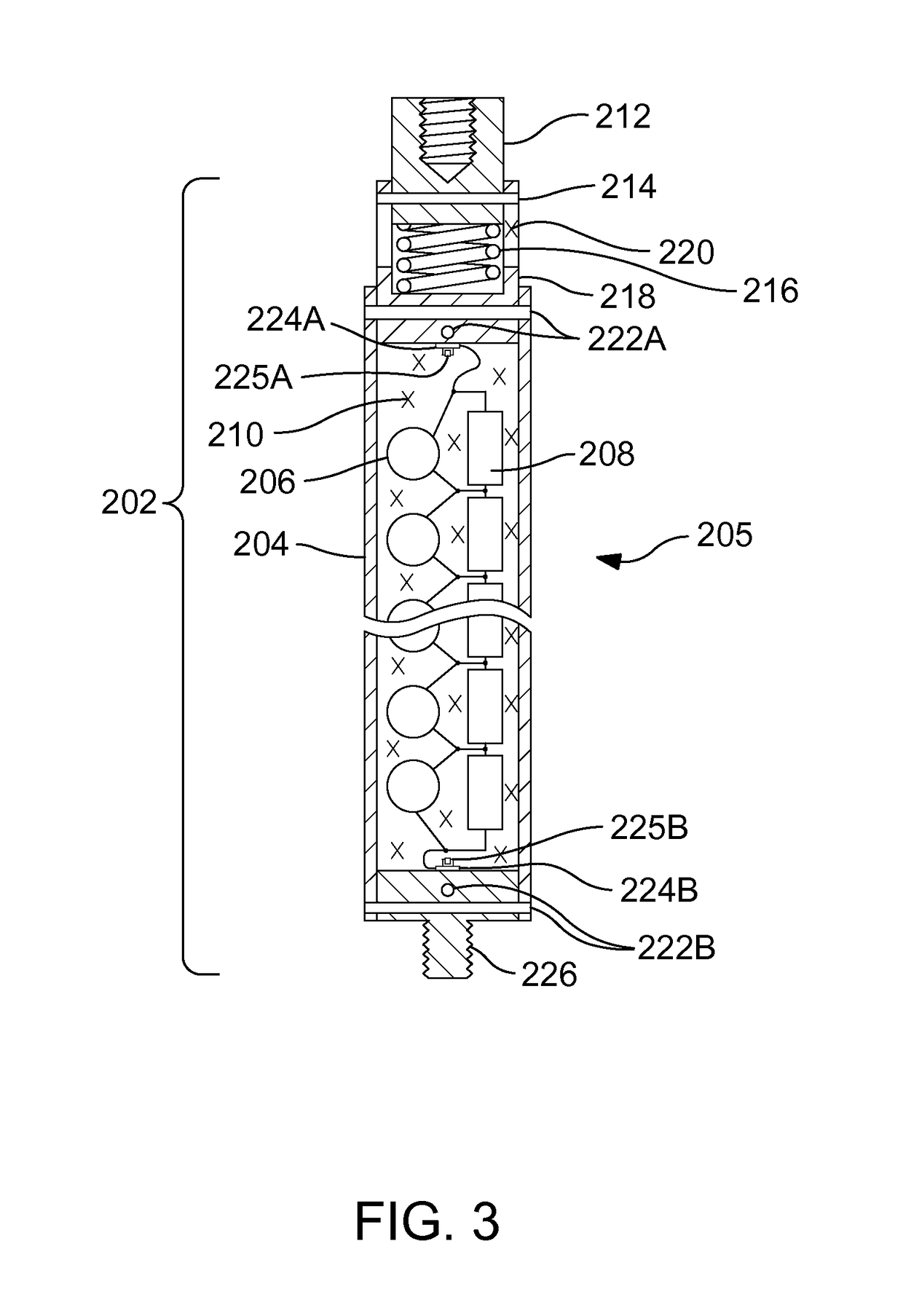
A double break vacuum interrupter includes a first contact system with an annular stationary contact, which is engaged by a primary moving contact with the moving contact rod extending through the primary moving contact and through the opening of the annular stationary contact. A second contact system includes a secondary moving contact disposed on an end of the moving contact rod, which engages and operates a floating contact on the same axis. Both contact systems are enclosed in a sealed envelope. A mechanical adjustment system is provided for the floating contact, which controls its range of motion. The mechanical adjustment system allows the first and second contact systems to engage at approximately the same time. A system of capacitors and resistors is provided to balance the voltage between the first and second contact systems to provide more efficient interruption of the electric current.

Description

BACKGROUND OF THE INVENTION[0001]1. Field of the Invention[0002]The present invention relates to the field of high voltage vacuum switches and circuit interrupting devices and more particularly to a double break vacuum switch or vacuum interrupter with two contact breaks connected in series and driven by a single contact rod.[0003]2. Discussion of the Prior Art[0004]A number of vacuum prior art arrangements are directed to provide a vacuum interrupter with two or more contacts within the same envelope as illustrated in U.S. Pat. Nos. 3,250,880; 3,405,245; 4,107,496; 4,246,458 and 6,476,338 B2. The first three cited patents present devices in which two moving contact structures must be moved in opposite directs to achieve two series contact breaks, necessitating a complex and costly operating mechanism. The latter two patents represent devices that rely on the transfer of the electric arc to one or more sets of auxiliary contacts as the moving contact is drawn past them. This can res...

Claims


Application Information

Patent Timeline
Patent Type & Authority Patents(United States)
IPC IPC(8): H01H33/666
CPCH01H33/666H01H33/143H01H33/664H01H33/16H01H33/6647H01H33/42H01H33/24
Inventor GLASER, MICHAEL DAVID
Owner GLASER MICHAEL DAVID
Learn More