Systems and methods of high resolution three-dimensional imaging

a three-dimensional imaging and high-resolution technology, applied in the field of three-dimensional imaging systems and methods, can solve the problems of inability of fpas by nature to detect color, inability of fpas to obtain information about the distance (z) of an object from the fpa, and inability to use complex, high-speed, expensive read-out circuits, etc., and achieve high-resolution results

Active Publication Date: 2013-06-25
NLIGHT INC
View PDF26 Cites 87 Cited by
  • Summary
  • Abstract
  • Description
  • Claims
  • Application Information

AI Technical Summary

Benefits of technology

[0023]In some embodiments, at least one of the first and second images contains a region of maximum intensity, wherein the means for generating comprises a sensor array having a saturation limit, and wherein the system is configured to enhance a dynamic range of the three dimensional image by increasing an energy of the light pulse above the saturation limit of the sensor array.

Problems solved by technology

However, most FPAs by their nature cannot detect color, only the presence and quantity of light.
Additionally, FPAs are limited to collecting information about light emanating from a scene in two dimensions, horizontal (x) and vertical (y), in front of the imaging device, often referred to as the field-of-view (FOV).
Most FPAs cannot, by themselves, obtain information about the distance (z) of an object from the FPA without the use of complex, high speed, expensive read-out circuits.
Both types of techniques typically are computational intensive, provide only limited information about the three dimensional features of a scene, and may be unsuitable for moving objects.
Additionally, stereoscopy typically requires precise knowledge of the relative position and angle at which the multiple two-dimensional images are obtained and so requires extensive calibration procedures and limited flexibility.
The multiple views also means that more lines of sight will be obscured.
This limits the use of such system in uncontrolled environments, can significantly increase the cost of any implementation, and limits the accuracy and precision of any calculated distance values.
As such, the maximum scanning speed may be limited by the amount of time required to make a measurement at each point, and the speed of the mirror or beam steering element.
Some such laser scanners are limited to processing tens of thousands to hundreds of thousands of points per second.
Therefore, obtaining a high resolution image of a complex scene may take a large amount of time, although lowering the resolution of the image may reduce the time required to obtain the image.
Image quality also may be degraded by performance drift during the scan, or motion within the scene.
However, the systems and methods disclosed by Taboada have limited applicability, some of which are discussed further below.
Although widely used for laser applications, Pockels cells traditionally have been viewed as having significant limitations, rendering such devices unsuitable for optical switching in other types of applications.
However, typical Pockels cells may only effectively modulate incident light deviating by less than about 1 degree from the surface normal, significantly limiting their use in such applications.
The electronics required to generate such fields may be expensive and cumbersome.
Reducing the thickness of the electro-optic crystal to bring the electrodes closer together may reduce the voltage, but also may reduce the clear aperture of the Pockels cell and may cause vignetting, e.g., loss of information at the edges of the image, reducing image quality.

Method used


Image

  • Systems and methods of high resolution three-dimensional imaging
  • Systems and methods of high resolution three-dimensional imaging
  • Systems and methods of high resolution three-dimensional imaging

Examples


Embodiment Construction

1. Overview

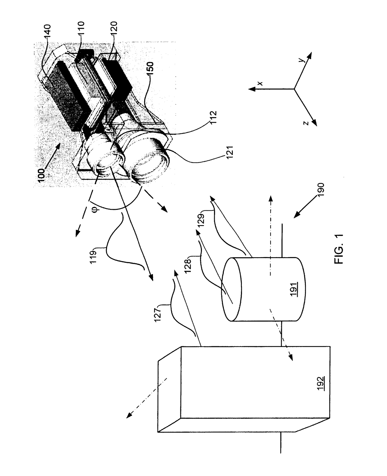
[0050]Embodiments of the invention provide systems and methods for obtaining high resolution images of scenes, including wide field of view scenes. Specifically, the systems and methods may simultaneously record three dimensional position information for multiple objects in a scene with high spatial and distance resolution, along with intensity (grey-scale or color) information about the scene. This information, both coordinate and intensity, is recorded for every pixel in an array of pixels for each image. The intensity and position information are combined into a single three-dimensional image that approximates a human view of the scene, and which further records the three-dimensional coordinates of the shape and relative position of each object in the scene. A series of such images may be acquired in similar fashion to a digital video camera, providing a “movie” of changes in the scene over time, each three-dimensional image in the movie being referred to as a frame. I...


PUM


Abstract

Embodiments of the invention provide systems and methods for three-dimensional imaging with wide field of view and precision timing. In accordance with one aspect, a three-dimensional imaging system includes an illumination subsystem configured to emit a light pulse with a divergence sufficient to irradiate a scene having a wide field of view. A sensor subsystem is configured to receive over a wide field of view portions of the light pulse reflected or scattered by the scene and including: a modulator configured to modulate as a function of time an intensity of the received light pulse portion to form modulated received light pulse portions; and means for generating a first image corresponding to the received light pulse portions and a second image corresponding to the modulated received light pulse portions. A processor subsystem is configured to obtain a three-dimensional image based on the first and second images.

Description

CROSS-REFERENCE TO RELATED APPLICATIONS[0001]This application claims the benefit of the following applications, the entire contents of each of which are incorporated by reference herein:[0002]U.S. Provisional Patent Application No. 61 / 117,788, filed Nov. 25, 2008 and entitled “Method and Apparatus for a 3D Digital Imaging Device;”[0003]U.S. Provisional Patent Application No. 61 / 121,096, filed Dec. 9, 2008 and entitled “Method and Apparatus for Wide Field of View Large Aperture, Low Voltage Optical Shutter;” and[0004]U.S. Provisional Patent Application No. 61 / 166,413, filed Apr. 3, 2009 and entitled “Method and Apparatus for Large Divergence Laser Illuminator.”FIELD OF THE INVENTION[0005]This application generally relates to systems and methods of three-dimensional imaging.BACKGROUND OF THE INVENTION[0006]Digital electronics have made it possible to record a grey scale or color image of a scene, as a still image, as a series of still images, or as a video. A video is a series of stil...

Claims


Application Information

Patent Timeline
Patent Type & Authority Patents(United States)
IPC IPC(8): H04N13/02G01S7/486G01S7/4865G01S17/10G01S17/89G01S17/894
CPCG01S7/4816G01S17/89H04N13/0207G01S7/4865G01S17/10G01S7/484G01S7/486H04N13/0253H04N13/204H04N13/207H04N13/254H04N13/296G01S17/894
Inventor BANKS, PAUL S.
Owner NLIGHT INC
Why Eureka
Try Eureka