Multi-stage amplifier

a multi-stage amplifier and amplifier technology, applied in the field of amplifier stages, can solve the problems of limiting the maximum number of amplifiers which may be combined, affecting the performance of the amplifier, so as to achieve the effect of saving cost and space, avoiding performance loss, and high accuracy

Active Publication Date: 2013-07-02
SNAPTRACK
View PDF7 Cites 25 Cited by
  • Summary
  • Abstract
  • Description
  • Claims
  • Application Information

AI Technical Summary

Benefits of technology

[0026]An advantage of the invention is that cost and space savings are achieved by separating out the two control loops. The low frequency control loop, which is relatively slow, is separated out from the high frequency control loop. The low frequency control loop is provided as a common control loop for a set of amplifiers. The common control loop can be adapted to be high-powered, to deliver an output to multiple amplifiers, without suffering a loss of performance. An individual high frequency loop is provided for each amplifier of the set. The provision of an individual high frequency loop for each amplifier allows the high accuracy benefits provided by advantageous arrangements to be substantially maintained, without incurring significant overheads in consuming space and an increased component count by replicating circuitry.

Problems solved by technology

In the prior art highly accurate tracking power supply arrangement found in United Kingdom Patent No. 2398648, if the power supply stage is adapted for a corporate structure to deliver a power supply to n power amplifiers, then the power of each of the low frequency loop and the high frequency loop must be increased by a factor n. This has a negative effect on performance.
Layout problems may arise on the circuit board, with longer tracks needed to some power amplifiers.
The maximum number of amplifiers which may be combined may also be restricted due to physical constraints of the power amplifiers on the feed network through which the modulated supply is delivered.
This requires a large amount of replication of circuits.
This adds to the cost and size of the implementations, and thus introduces of its own inefficiencies.
In this arrangement, to achieve the benefits of an efficient, highly accurate tracking power supply for each single amplifier requires a high component count and associated cost.
As noted above, in a corporate structure with n amplifiers and n associated modulated supplies, regardless of the specific modulated supply implementations, disadvantages of performance, cost and size may be encountered.

Method used


Image

  • Multi-stage amplifier
  • Multi-stage amplifier
  • Multi-stage amplifier

Examples


Embodiment Construction

[0034]The invention is now described below by way of example with reference to non-limiting embodiments.

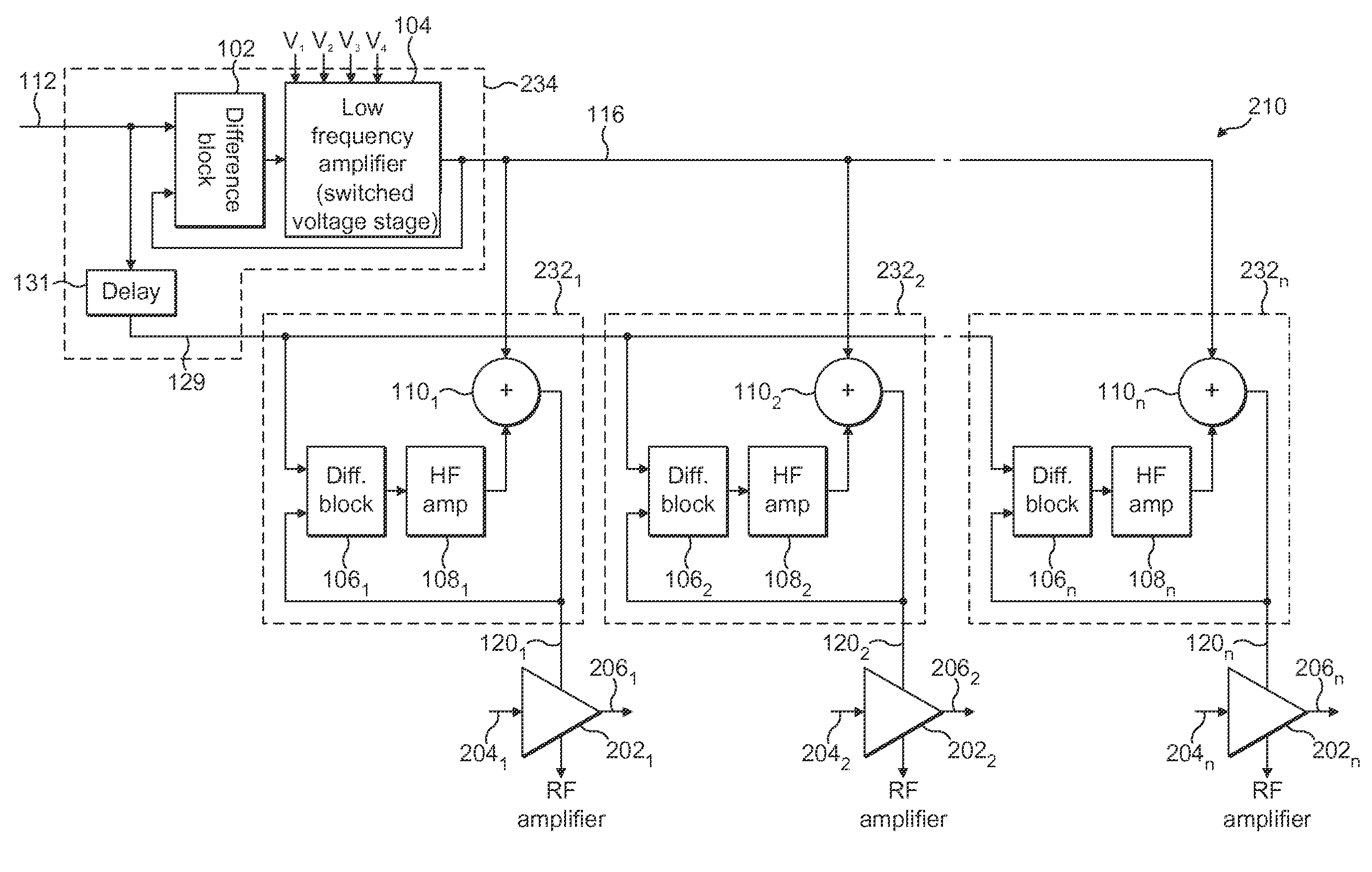
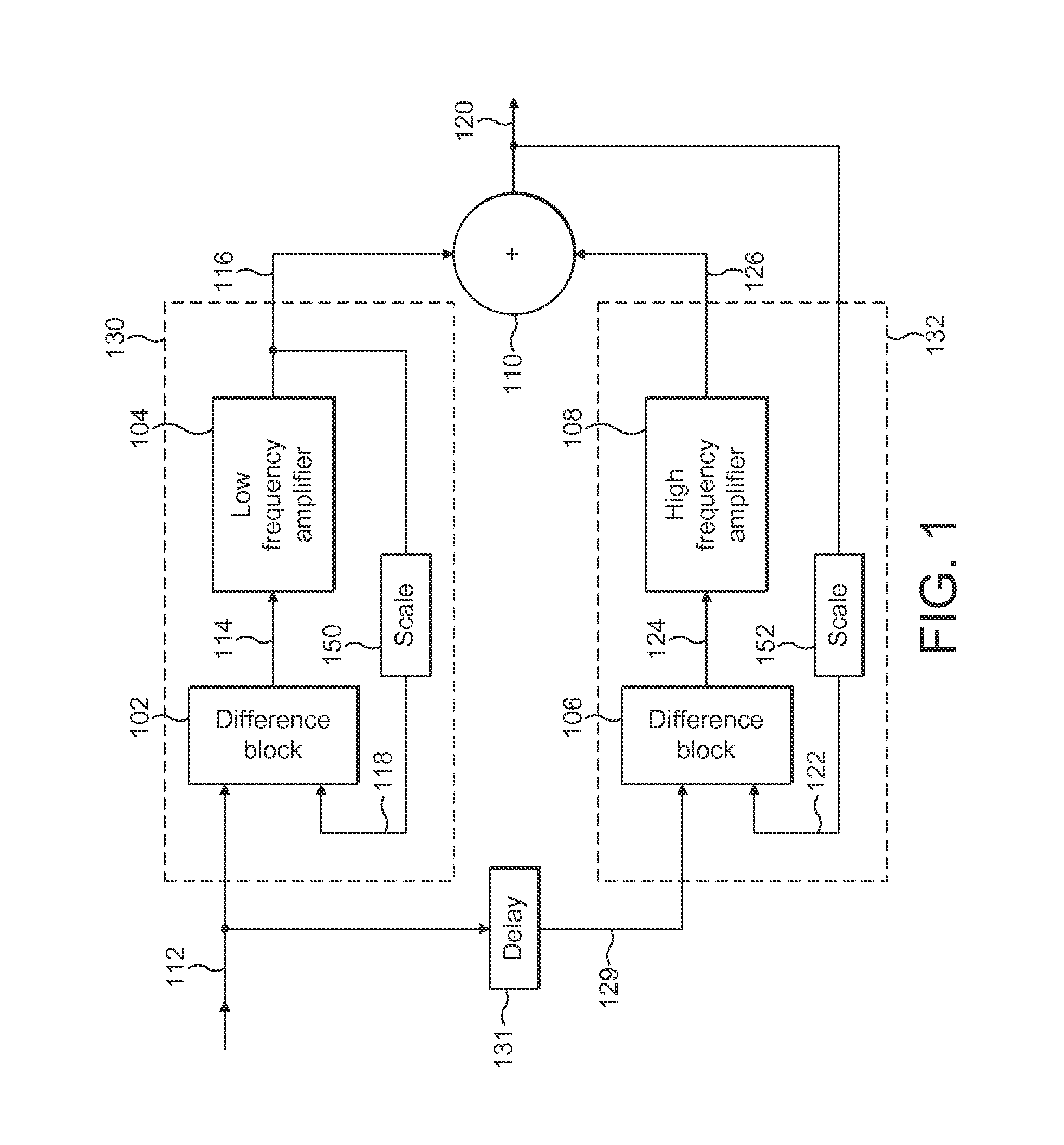
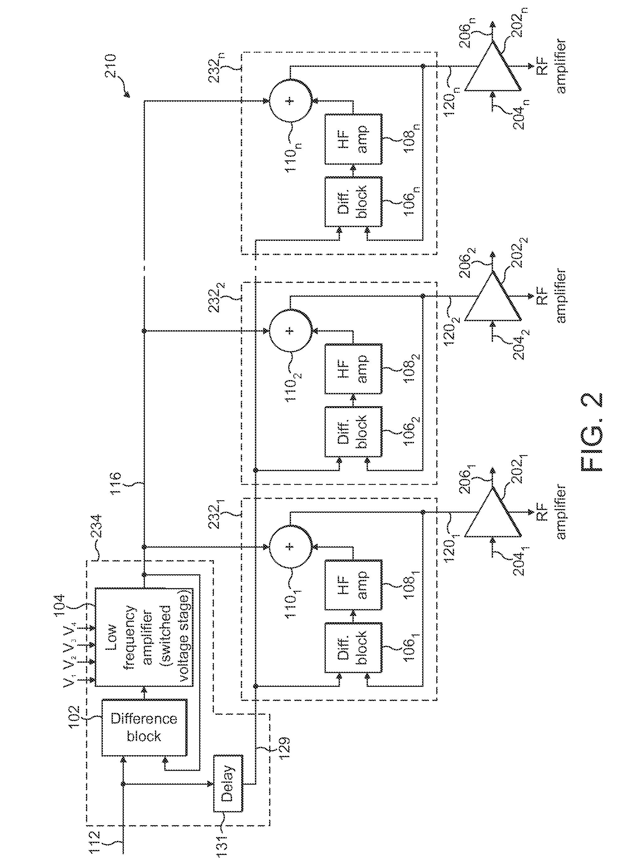
[0035]FIG. 1 illustrates an exemplary dual-loop control system in accordance with the principles set out in United Kingdom Patent No. 2398648. United Kingdom Patent No. 2398648 is incorporated herein by reference. A difference block 102 and a low frequency amplifier 104 define a first path 130. The first path may also be referred to as a first control path, or a main path. A difference block 106 and a high frequency amplifier 108 define a second path 132. The second path may also be referred to as a second control path or an error correction path. In general, the second path removes an error from the first path, as will be understood from the following description.

[0036]A summer or combiner 110 is provided to combine the two control paths. The objective of the control system is to provide on an output line 120 a signal which is an accurate replica of an input signal provided on li...


PUM


Abstract

There is disclosed a power supply stage, and a corresponding method, comprising: a plurality of amplifiers for amplifying an input signal, each amplifier receiving a power supply voltage; a common selection means for selecting one of a plurality of power supply voltages in dependence on a reference signal representing a desired power supply voltage; and a plurality of adjusting means, corresponding to the plurality of amplifiers, adapted to generate an adjusted selected power supply voltage for a respective amplifier tracking the reference signal in dependence on the one selected power supply voltage and the reference signal.

Description

BACKGROUND TO THE INVENTION[0001]1. Field of the Invention[0002]The present invention relates to amplification stages for providing a modulated supply voltage, and particularly to such amplification stages organised to provide higher power than can be achieved in a single stage by using an arrangement known as a ‘corporate structure’ amplifier.[0003]2. Description of the Related Art[0004]It is known to provide a modulated power supply for providing a supply voltage to an amplification stage, such as a radio frequency (RF) amplification stage. An example of a particularly advantageous modulated power supply stage can be found in United Kingdom Patent No. 2398648.[0005]In this advantageous modulated power supply stage there is provided an efficient technique for tracking the supply voltage to an RF amplifier in dependence on the RF input signal to be amplified by the amplifier. A first control loop tracks the envelope of the input signal, representing a desired supply voltage for the ...

Claims


Application Information

Patent Timeline
Patent Type & Authority Patents(United States)
IPC IPC(8): H03G3/20
CPCH03F1/0211H03G3/004H03F3/45076
Inventor WIMPENNY, GERARD
Owner SNAPTRACK
Why Eureka
Try Eureka