

Method of producing cold-worked centrifugal cast tubular products
a centrifugal cast tubular and product technology, applied in the direction of engine components, metal-working apparatus, forging hammers, etc., can solve the problems of limiting the choice of tubular components that can stand, grain sizes and may contain casting defects, and deeper wells contain higher temperatures and pressures
- Summary
- Abstract
- Description
- Claims
- Application Information
AI Technical Summary
Benefits of technology
Problems solved by technology
Method used
Image

Examples
Embodiment Construction
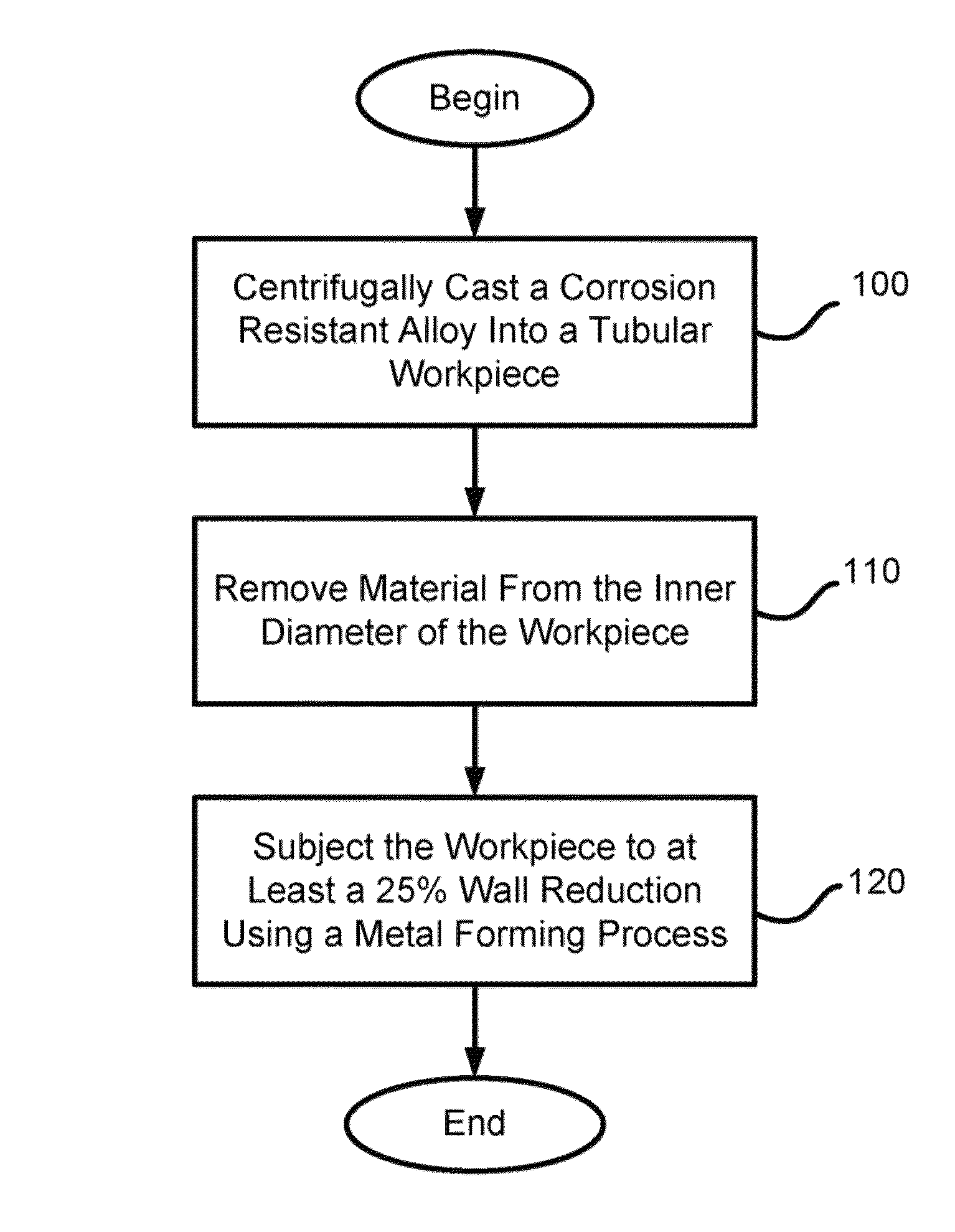
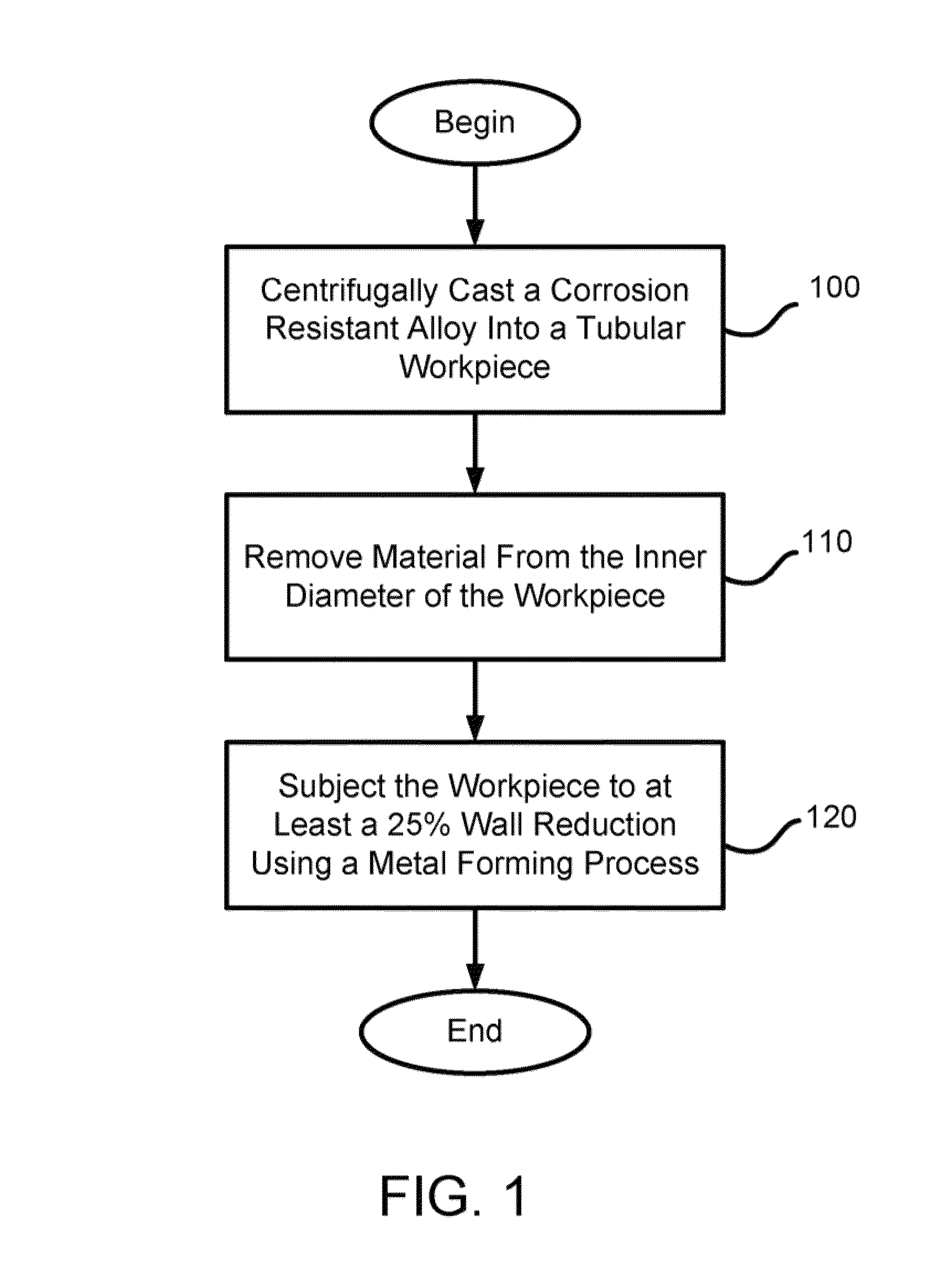
[0008]In accordance with one embodiment of the invention, a method of producing a seamless, tubular product includes centrifugally casting a corrosion resistant alloy into a tubular workpiece having an inner diameter and an outer diameter. The method then removes material from the inner diameter of the workpiece and subjects the workpiece to at least about a 25% wall reduction at a temperature below a recrystallization temperature of the workpiece using a metal forming process. The metal forming process includes radial forging, rolling, pilgering, and / or flowforming.
[0009]In some embodiments, the wall reduction is at least about 35% or at least about 50%. The 35% or 50% wall reduction may include at least two reductions. The first reduction may be at least about a 25% wall reduction. The corrosion resistant alloy may include a stainless steel alloy, a titanium-based alloy, a nickel-based alloy, a cobalt-based alloy and / or a zirconium-based alloy. The method may further include remov...
PUM
| Property | Measurement | Unit |
|---|---|---|
| Fraction | aaaaa | aaaaa |
| Fraction | aaaaa | aaaaa |
| Fraction | aaaaa | aaaaa |
Abstract
Description
Claims
Application Information