
Method for crack and fracture modeling in directed surfaces

a technology of directed surface and fracture morphology, which is applied in the direction of design optimisation/simulation, instruments, and mechanical means, can solve the problems of inability to obtain reliable information with any reliable amount of certainty, the number of molecules required for md simulation capable of modeling practical engineering fracture problems, and the inability to accurately model the actual location of the matrix. the information lost in the idealization of the fiber becomes critical, and the number of molecules required for md simulation is prohibitively larg

Active Publication Date: 2013-07-09
UNIV OF SOUTH FLORIDA
View PDF3 Cites 7 Cited by
  • Summary
  • Abstract
  • Description
  • Claims
  • Application Information

AI Technical Summary

Benefits of technology

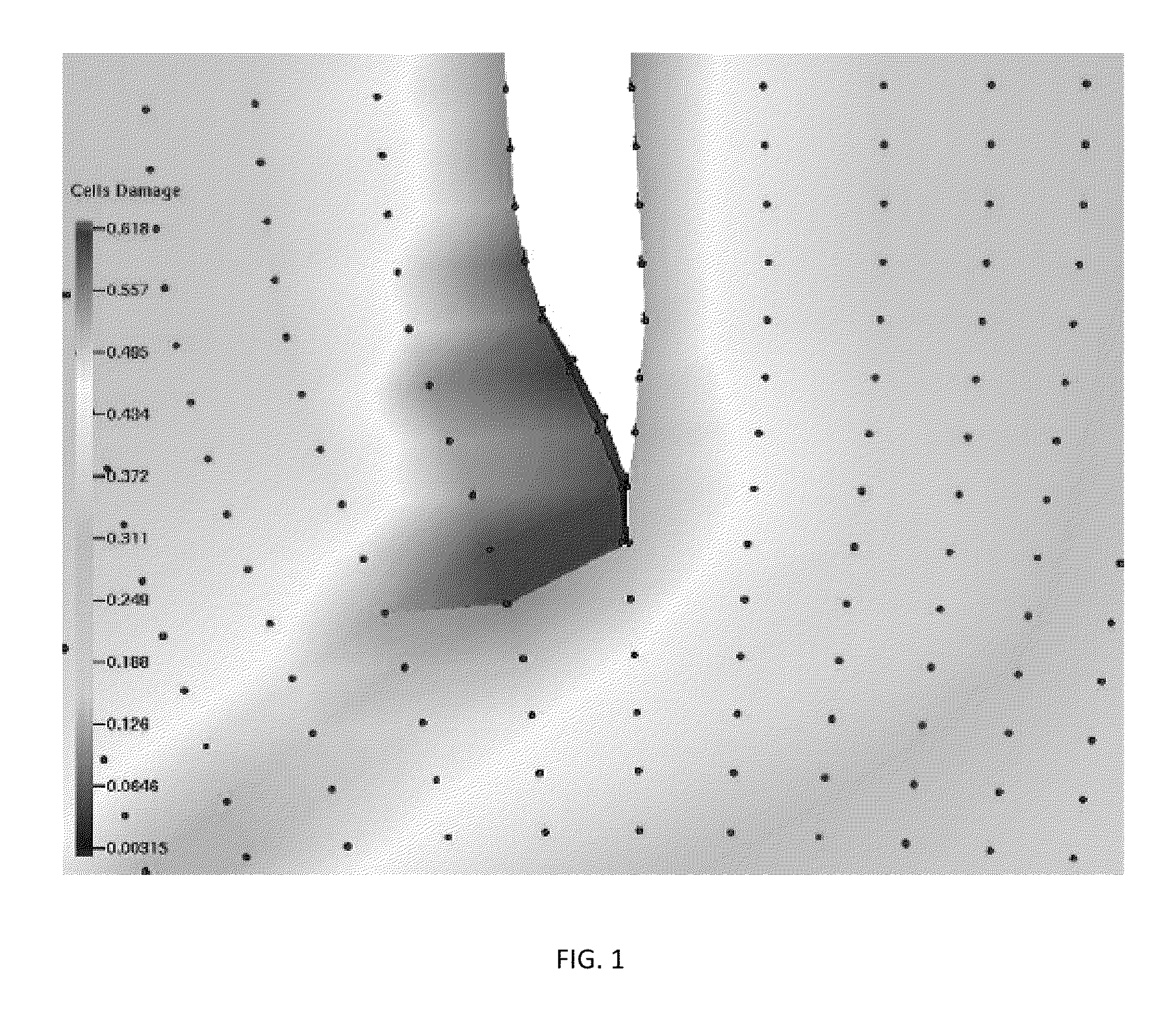
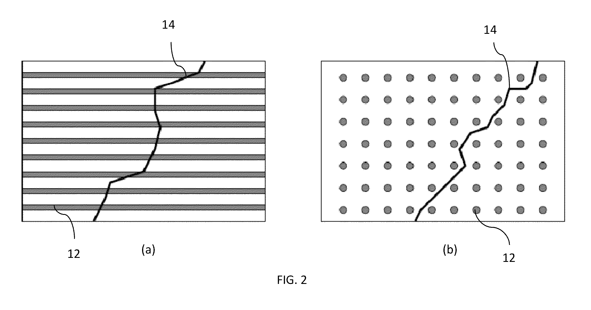
The patent text describes a new method for solving the continuum equations that incorporates discontinuities, such as cracks, in a body using a collection of interacting particles. This method allows for the modeling of cracks in three-dimensional directed surfaces and the identification of emergent cracks. The key technique involves particle splitting, dynamic changing of the topology, and the ability to accommodate any failure mechanism, including external rules-based models. The method can be extended to multiple stacked directed surfaces and provides many different crack propagation and morphology capabilities.

Problems solved by technology

However, the number of molecules required for MD simulations capable of modeling practical engineering fracture problems is prohibitively large.
Even if the small scale of the fibers could be represented, the actual location in the matrix is knowledge that is difficult (if not impossible) to obtain with any reliable amount of certainty.
However, when failure is to be modeled, especially cracking, the information lost in the idealization of the fibers becomes critical.
Cracking models based on continua will not predict the correct crack morphology due to the absence of actual fibers.
In mesh-based analysis methods, the mesh orientation may influence the crack direction, but it may conflict with the physical requirements dictated by the fiber orientation.

Method used


Image

  • Method for crack and fracture modeling in directed surfaces
  • Method for crack and fracture modeling in directed surfaces
  • Method for crack and fracture modeling in directed surfaces

Examples


Embodiment Construction

[0029]The Reproducing Kernel Particle Method (RKPM) [1] provides a method to construct a function basis for use in Galerkin solutions to partial differential equations without using a mesh; instead, the RKPM method uses local and dynamic interactions between nodes (particles). Since a mesh is not required to form the function space, it can evolve dynamically; in particular, it can be adjusted as the material topology changes. The RKPM method constructs a local interpolation field centered at each node that is based on local interaction with neighboring nodes. By introducing a visibility condition during a calculation, one can selectively limit the interaction between nodes to effectively cut the material. A version applicable to two-dimensional problems was presented in [2].

[0030]The node splitting method uses information determined from either the constitutive model or other, possibly external, source, to determine when a node should be split. Based upon this damage measure, the cr...


PUM


Abstract

A method for three-dimensional crack propagation, morphology, and initiation suited to directed surfaces, or stacks of directed surfaces. An external damage measure and failure criteria can be incorporated, as well as a rule-based crack direction and morphology capability. This method is ideal for laminated composites. Further, the use of external damage and failure, and rule-based crack propagation, this method is ideal for multi-scale modeling and use in applications where knowledge and rules are necessary or desirable for guiding, driving, or influencing failure modes, directions, or other situations that are not directly incorporated into the governing mechanical equations.

Description

CROSS REFERENCE TO RELATED APPLICATION[0001]This application claims priority to U.S. provisional patent application No. 61 / 256,018, entitled “A METHOD FOR CRACK AND FRACTURE MODELING IN DIRECTED SURFACES,” filed on Oct. 29, 2009, the contents of which are hereby incorporated by reference.BACKGROUND OF THE INVENTION[0002]1. Field of the Invention[0003]This invention relates to a three dimensional crack and fracture morphology and propagation method for single and stacked directed surfaces that naturally incorporates external information.[0004]2. Description of the Prior Art[0005]A physical phenomenon, such as a fracture, fundamentally occurs in a discontinuous fashion. However, most methods for solving structural mechanics problems (e.g. the finite element method) are formulated to solve for continuous field variables. To model a crack in a continuum model requires embedding some model of discontinuity into the continuous formulation. Numerous approaches using this methodology have b...

Claims


Application Information

Patent Timeline
IPC IPC(8): G01N19/08
CPCG01N2203/0062G01N2203/0218G01N2203/0647G06F30/20
Inventor SIMKINS, JR., DANIEL C.
Owner UNIV OF SOUTH FLORIDA
Learn More