Surveillance camera

a surveillance camera and camera body technology, applied in the field of surveillance systems, can solve the problems of increased bit errors, signal loss, crosstalk, etc., and achieve the effects of discharging rf energy trapped in the ring structure, minimizing impedance mismatching, and eliminating crosstalk issues

Active Publication Date: 2013-07-09
PELCO INC
View PDF17 Cites 3 Cited by
  • Summary
  • Abstract
  • Description
  • Claims
  • Application Information

AI Technical Summary

Benefits of technology

[0006]The present invention enables the use of a slip ring in a 360 degree full rotation pan / tilt / zoom (PTZ) camera to conduct the two differential signals in a 100BASE-T Ethernet transmission line with the use of only nine slip ring pins. The Ethernet transmission structure uses nine pins on nine sequential rings. Four pins carry the dual differential 100BASE-T Ethernet signal pairs. The remaining five pins of the set are used for RF reference plane lines that are associated with the RF ground plane of the design. The five RF reference plane lines are used to eliminate crosstalk issues between the Ethernet lines, provide a structure which minimizes impedance mismatching, and includes series resistive damping elements to dissipate RF energy trapped in the ring structure, which lowers the quality factor or Q factor of ringing on the data bits in the 100BASE-T data stream. This technique maximizes the signal integrity of the Ethernet stream, and provides minimum bit error rate issues in the slip ring 100BASE-T Ethernet communication path. This invention allows dual purpose use of the five RF reference plane slip ring lines, such that all five can also carry DC power and low frequency signals, which decreases the number of slip ring rings required in any given design. This invention allows the video signal to be compressed on the rotating structure before it reaches the slip ring. Decreasing the bandwidth of the video information crossing slip ring, by compression on the rotating structure, allows the use of low bandwidth, low cost slip ring parts in the design, with no limit to the camera video resolution as long as the bandwidth of the compressed video does not exceed Ethernet 100BASE-T capability.

Problems solved by technology

When prior art movable cameras employing slip rings attempt to use high definition cameras and fast Ethernet signals, they generally suffer from increased bit errors, crosstalk, and even total loss of signal.

Method used


Image

  • Surveillance camera
  • Surveillance camera
  • Surveillance camera

Examples


Embodiment Construction

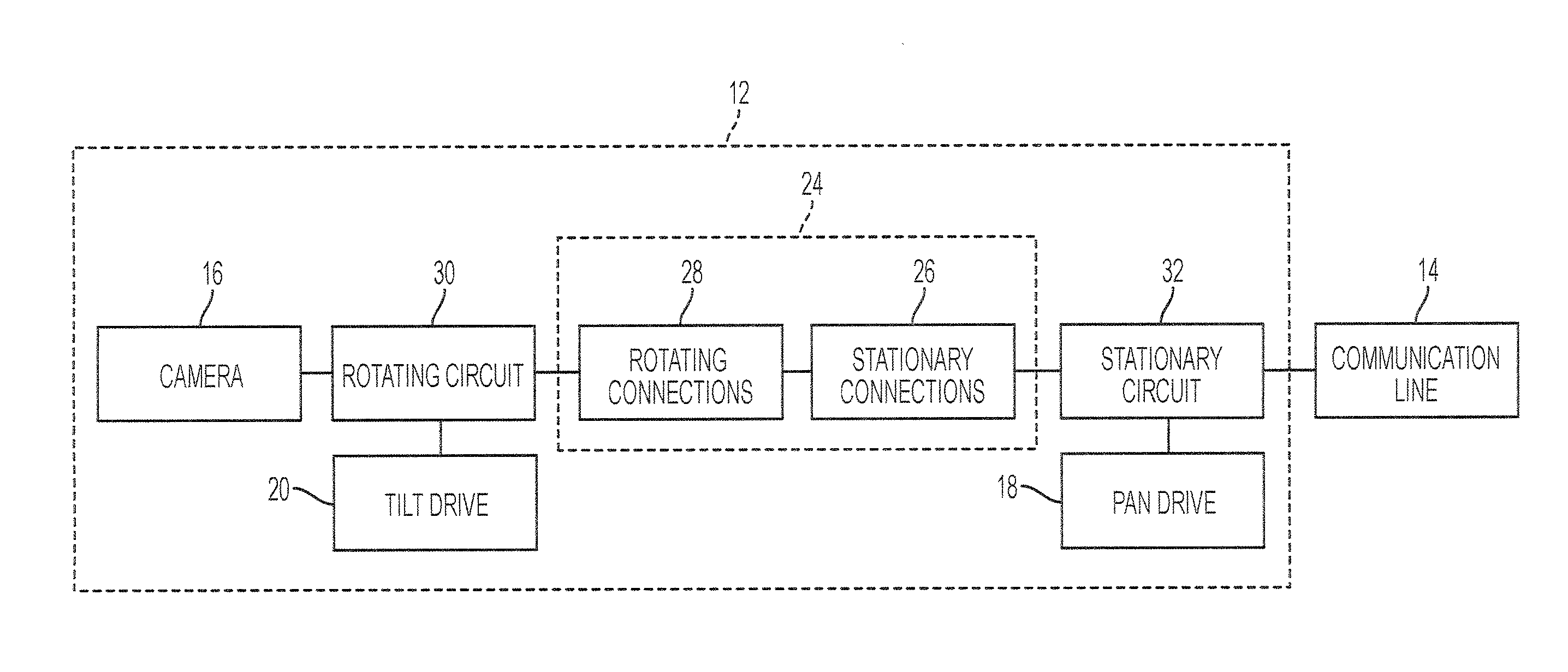
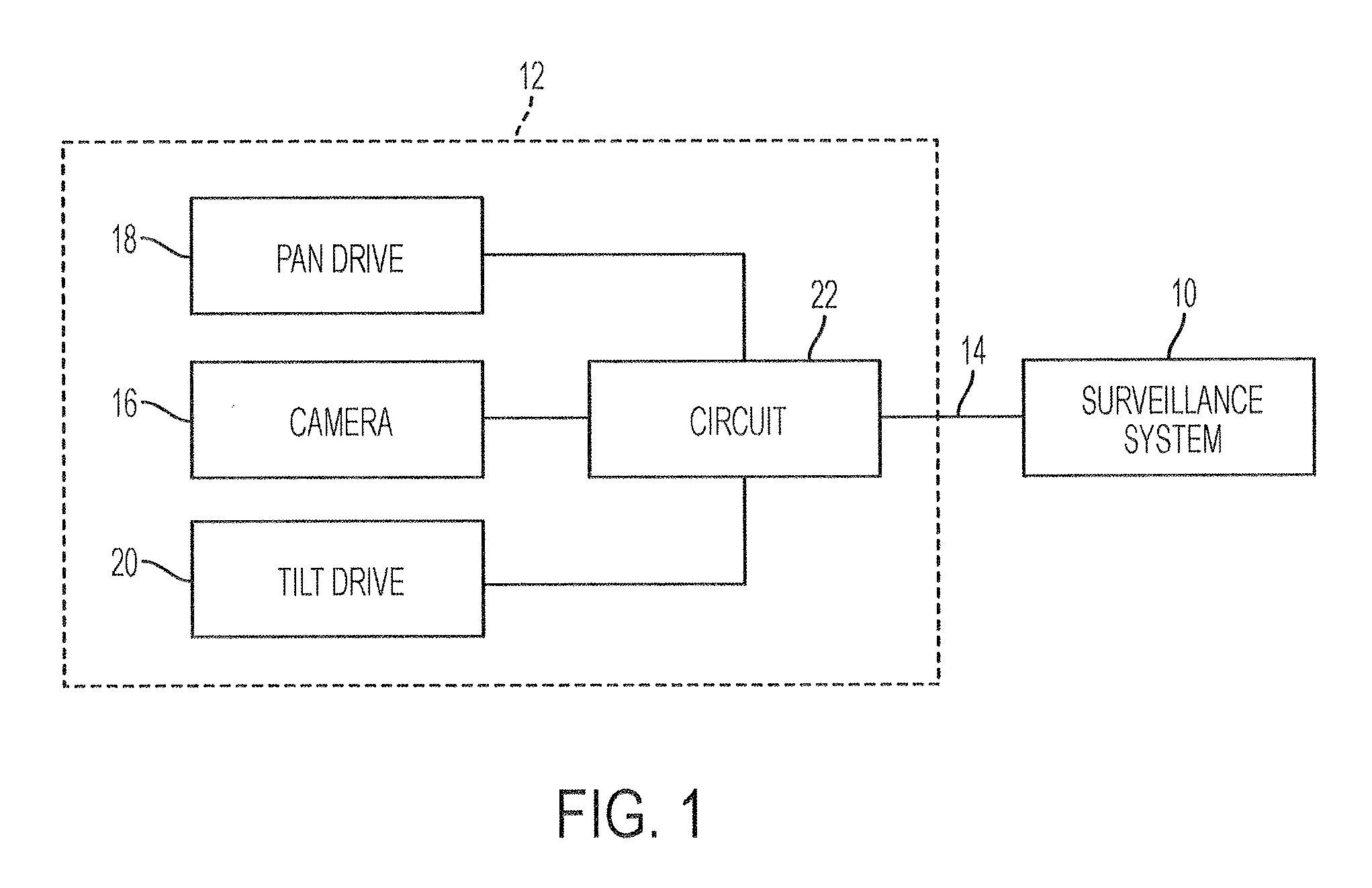
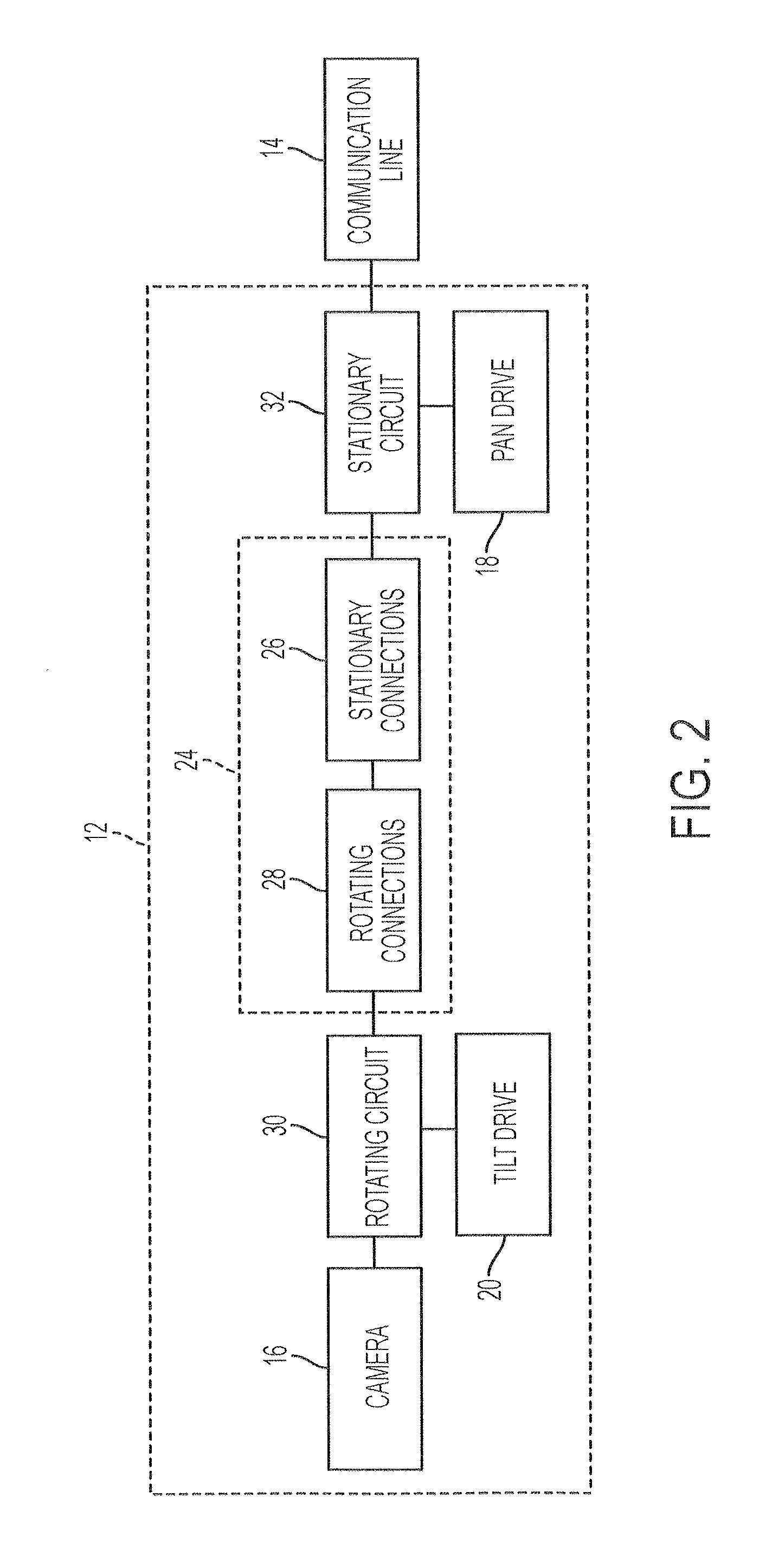
[0012]Referring to FIG. 1, a video surveillance system 10 is connected to surveillance camera 12 by communication line 14, which can be, for example, an Ethernet cable such as Category 5 (CATS) running 100BASE-T over four wires arranged in two twisted pairs of the CATS cable with, for example, one pair for transmitting control signals from surveillance system 10 to surveillance camera 12 and the other pair for receiving video signals from surveillance camera 12.

[0013]Surveillance camera 12 has a camera 16, which can be a mega pixel camera having a high definition of, for example, 720 p or 1080 p. Surveillance camera 12 can be a PTZ type camera with pan drive 18 for rotating surveillance camera 12 in a horizontal plane and tilt drive 20 for moving surveillance camera 12 in a vertical plane. Circuit 22 controls pan drive 18 and tilt drive 20 based on control signals provided by surveillance system 10 over communication line 14 as is know in the art. Circuit 22 performs various other f...


PUM


Abstract

A surveillance camera includes a slip ring having electrical connections for Ethernet protocol signals and a RF reference plane. A first circuit is located on a rotating portion of the surveillance camera and electrically connected to the camera for compressing signals generated by the camera and for converting the signals generated by the camera to Ethernet protocol signals. The slip ring has a stationary portion and a rotating portion, each with a corresponding plurality of electrical connection. An RF reference plane is located on the stationary portion of the surveillance camera and electrically connected to a first subset of the plurality of electrical connections of the stationary portion of the slip ring. A second subset of the plurality of electrical connections of the stationary portion of the slip ring conducts the Ethernet protocol signals and is arranged in alternation with each electrical connection of said first subset.

Description

CROSS-REFERENCE TO RELATED APPLICATION[0001]N / ASTATEMENT REGARDING FEDERALLY SPONSORED RESEARCH OR DEVELOPMENT[0002]N / ABACKGROUND OF THE INVENTION[0003]This invention relates to surveillance systems and, in particular, to a movable surveillance camera capable of utilizing fast Ethernet signals in a video surveillance system.[0004]Surveillance systems often include movable cameras, which are referred to in the industry as pan / tilt / zoom cameras or PTZ cameras. The PTZ cameras employ circuitry and drive mechanisms for panning, tilting, and zooming the camera. A surveillance camera assembly with 360 degree pan motion requires a rotational joint that can conduct electrical power and signals between the camera on the rotating structure and the electronics on the stationary structure. Typical designs use a slip ring to realize this power / signal rotational joint. Such slip rings have generally been used in movable analog camera assemblies to transmit the analog video signals across the slip...

Claims


Application Information

Patent Timeline
Patent Type & Authority Patents(United States)
IPC IPC(8): H04N9/47
CPCH04N7/183G08B13/1963G08B13/19636H04B3/32
Inventor WEBB, CLIFFORD
Owner PELCO INC
Why Eureka
Try Eureka