Sensor system, method for operating a sensor system, and method for manufacturing a sensor system

a sensor system and sensor technology, applied in the direction of fluid pressure measurement, pressure difference measurement between multiple valves, instruments, etc., can solve the problems of comparatively complicated and expensive manufacturing and installation of capping, diaphragm region may be used, etc., and achieve high aspect ratio

Inactive Publication Date: 2013-07-16
ROBERT BOSCH GMBH
View PDF14 Cites 6 Cited by
  • Summary
  • Abstract
  • Description
  • Claims
  • Application Information

AI Technical Summary

Benefits of technology

[0005]The sensor system according to the present invention, the method according to the present invention for operating a sensor system, and the method according to the present invention for manufacturing a sensor system have the advantage over the related art that an absolute pressure may be measured in a comparatively simple and cost-effective manner, the absolute pressure to be measured including in particular a comparatively high pressure. In addition, as the result of integrating the second diaphragm region and the cavern into the first diaphragm region, a comparatively compact sensor system is possible, and capping of the sensor may be dispensed with completely, so that the manufacturing costs may be reduced and system integration is greatly simplified; for the integration of the sensor system into a vehicle, compactness and ease of integration are of great technical and economic interest due to the limited available installation space in the vehicle. This is achieved by integrating the second diaphragm region and the cavern into the material of the first diaphragm region, so that the first diaphragm region carries out a relative pressure measurement, preferably between a first pressure on the first side and a second pressure on the second side of the substrate or in a trench on the second side due to a deformation perpendicular to the main plane of extension, while an absolute pressure measurement between the second pressure and a third pressure, i.e., a reference pressure, in the cavern is possible due to the integration of the second diaphragm region and the cavern into the first diaphragm region. The cavern preferably extends essentially parallel to the main plane of extension. In addition, the cavern in particular is enclosed completely, i.e., in all spatial directions, by the first diaphragm region, so that no additional substrate surface area besides the first diaphragm region is necessary for carrying out the absolute pressure measurement.

Problems solved by technology

One disadvantage of this sensor is that the diaphragm region may be used only for determining a relative pressure difference between the pressure in the open cavern and the pressure on the other side of the diaphragm region, i.e., the side facing away from the open cavern, while for determining an absolute pressure in the open cavern, hermetically sealed capping must be provided on the other side of the diaphragm region.
The manufacture and installation of the capping is comparatively complicated and costly due to the requirements for seal-tightness of the capping.

Method used


Image

  • Sensor system, method for operating a sensor system, and method for manufacturing a sensor system
  • Sensor system, method for operating a sensor system, and method for manufacturing a sensor system
  • Sensor system, method for operating a sensor system, and method for manufacturing a sensor system

Examples


Embodiment Construction

. OF THE INVENTION

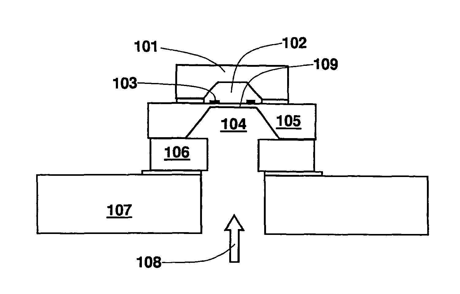
[0023]FIG. 1 illustrates a schematic side view of an absolute pressure sensor according to the related art, having a sensor substrate 105, a sensor cavern 104, and a sensor diaphragm 109, the sensor substrate 105 being connected to a glass base 106, and the glass base 106 being glued to a printed circuit board 107 with the aid of an adhesive. Printed circuit board 107 and glass base 106 each have an opening, so that a pressure 108 reaches sensor cavern 104 from a lower side of printed circuit board 107, and sensor diaphragm 109 is deformed as a function of pressure 108 and as a function of a reference pressure 102. This deformation is measured by piezoelectric resistors 103 on the upper side of sensor diaphragm 109. The upper side of sensor diaphragm 109 has a hermetically sealed capping 101 which is used to set known reference pressure 102. By setting known reference pressure 102 on the back side of diaphragm 109, the absolute value of pressure 108 may be determin...


PUM

PropertyMeasurementUnit
pressureaaaaaaaaaa
pressuresaaaaaaaaaa
voltageaaaaaaaaaa

Abstract

A sensor system, e.g., a pressure sensor system, includes a substrate having at least one trench on a first side. The trench is provided for forming a first diaphragm region on a second side opposite from the first side. In addition, a second diaphragm region and a cavern are integrated into the material of the first diaphragm region.

Description

BACKGROUND OF THE INVENTION[0001]1. Field of the Invention[0002]The present invention relates to a pressure sensor system.[0003]2. Description of Related Art[0004]Such sensor systems are generally known. For example, a sensor and a method for manufacturing a sensor are known from the published German patent application document DE 102 26 034 A1, the sensor including a semiconductor material having a first thickness, and having a second thickness in a diaphragm region, the second thickness being smaller than the first thickness. The sensor includes an open cavern in the diaphragm region due to the second thickness. The diaphragm region is deformable perpendicularly to the substrate as a function of the pressure in the open cavern, means being provided for measuring the deformation of the diaphragm region in the transition region between the first and the second thickness. One disadvantage of this sensor is that the diaphragm region may be used only for determining a relative pressure...

Claims


Application Information

Patent Timeline
Patent Type & Authority Patents(United States)
IPC IPC(8): G01L7/00H01L29/84
CPCG01L9/0045G01L13/025
Inventor AHLES, MARCUSBENZEL, HUBERTWEBER, HERIBERT
Owner ROBERT BOSCH GMBH
Why Eureka
Try Eureka